CIRCUIT
DESCRlPTlON
The
AG
power supplied
to
the
OCe150A
powers
the
meter boards
and
the
display
lights.
Dual
8
volt
secondaries
ern
the transformer
power
the
meter.
amps
separately, with each amplifier having its
own
rectifier
and
capacitive
filter. She
resulting
un-
regulated supplies
are
k
lO
volts.
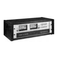
The
uniqueness
of
the
OC-150A
metering system
is
that
the
information
fed
to
the
mebevs
is
elecfrcani~al-
ly
derived.
Peaks
are
held
at
the
meter terminals
so
that
the
readout accuracy
dws
nQI
depend
an
metea
response
time.
To
accmplish this,
the
audio
signal
(from
thepwrer
amplifier
output),
goes
through
a
rectificaticrro
process
to
produce
a
series
sf
negative
pulses.
These
are pmeessad
by
a
uaity-gain
invefiing
op-amp
which
in
turn
drives
a
transistor stage.
The
output
of
the
transistor stage charges
the
peak
storag~
and
timing
RC
networks which
permit
the
unique
opera-
tion
of
the
circuitry.
$a3
reduce
leakage into the
storage network, the circuit
is
isolated through
a
pair
of
transistors
biased
as diodes.
The
voltage
im-
pressed
on
the
storage
network
drives another
unity
gain
IC
stage,
which
in
turn
drives
the
meter
move-
ment.
This final-stage
IC
incarporates
a$-FET
input
to provide
the
extremely
high
impedance
neded to
maintain
a
stable
voltage
in
the storage network.
An
auxiliaw
IC
stage provides compensation
for
thg
in-
put
sHseteurrenl
(in
the
picoamp
range)
and
the
out-
put
offset
voltage
of
the
finlaf
stage,
"fhr;
precise
ad-
justment required
is
dane
during
the
factory
sel~up
procedure, Peaks
stared
in
the
network
are
thus
held
until
a
discharge
transistar
is
turned
ogl
(by
the tim-
ing
circuit).
Using
this
overall
mnfiguration,
higher
peaks
ar@
always allowed
to
daminate
the
meter
movement,
and
peaks
can
be
held
with re35
than
Q.5
db
of
meter
drin
For
longer than
20
minutes
(ar
roughly
the
time
needed
to
play
one
side of
an
LP).
At
the
time
the peak storage netvvork
is
charged,
the
timing
network
is
also
charged
by
a
current
sauree
tumed
on
by
the
initial
transistor stage
sf
the
amp!
ifier.
The
positive voltage thus impressd
on
the.
timing
network
is
applied
to
the
inverling
input
sf
an
op-amp
camplarator
circu
if
a
The
comparator
main-
tains
a
negative output
a5
long
as
the
timing network
charge
is
positive.
In
the
VU
mode
this
charge is
removed
very
quickly
by
discl-rarging
the
netwsrrh
tkmugh
a
resisBor
to
the
-16
woft
supply, Re
hold
time
is
extremely
shsrt
and
the
meter
simply
averages
%he
siigna
t
level.
I
rz
the
peak
mode,
however,
the
nebork
may
kdischsrgd
tograund
(maximum
hord
time)
or
to
the
-10
volt
supply
(minimum
hold
time)
OP
any
wint
between
these
Wo
sxtremes, The
hold
time
csntaol
wsrks
by
varying
the
effedive
reference
voltage
discharging
the
timing
network.
When the
timing
network
is
su8icien"tly
discharged
for
its
voilage to
become
negative,
the
camparator
op-amp
switches
to
a
positive
output
which
turns on
the
discharge
transktsr
and
removes
the
drive to
the
meter,
if
the discharge circuit
is
referened
to
ground (meter
hold
control
at
the potential
on
the
nework
will
tllever
became
negative
and
the
hold
time
will consequently
ba
infinite*
(Hawever,
the
ac-
curacy
will
vary with the
drift,
as described
above.)
With
the
hold
time
control
referencing
thc
eixuit
lo
the
-10
volt
supply
$mine
hold),
the
neWork
wilil
dis-
charge
in
about
600
milfisecands.
Meter
calibration
is provided
by
a
pd
in
series with
the meter movement,
HEADPHONE
A"$lfEQslUQ\"O"OR
SWITCHES
Bwause
of
the relative efficiency
sf
most
headphones,
it.
Is
easy
ta
produce large sound
pressure
levels
with
low
or medium pwer
amplifiers.
A
200
was
amplifier
would
represent
a
"lethal
dose"
of
power
to
most
headphones. at
is
for this reason
that
Btkerauator~ are inserted
in
series
with
the
headphone
jacks
an
the front
pame!
of
the
8C-150As
Two
levels sf
attenuation
are
available,
17db
and
2463b.
The
attenuators are
activated
by
three-
position
slide
switches
on
the
reas
panel,
Tgs
illustrate the
usefugness
sf
the attenuators,
let's
set
up
a
typicaa
headphone
monitoring
system,
We?/
assume
an
impedance
of
8
ohm$
with an eMiciency
such
tlaat
3
volts
acradjs
the
8
ohm
impedance
produces
a
casmfa&abie
listening
!eve/.
Using
Ohm's
law
the
power
is
%
.I3
watts.
Now
if
we
WOW
td
switch
t~
the
%7db
aRenuation
position,
we
could
increase
the
voltage
ts
21.4
volts
and
still
keep
3
volts
acrsss
our
headphones, The
new
pswr
is
57.2
waHs.
Similarly,
by
using
the
24db
a"ctenuatiora
position,
the
voltage/poweb-
could
be increased
to
49,8
waits
08"
318
waEs.
 Loading...