Specifications
5-5
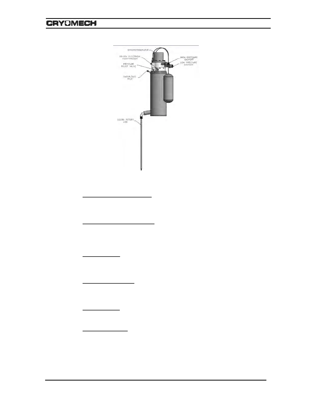
Figure 5-3: Helium Reliquefier
A. Cryorefrigerator (Cold Head)
The cold head is bolted to the top of the main assembly. An O-ring, located between the
main assembly and the cold head, seals the helium gas inside the main assembly.
B. 10-Pin Electrical Feedthrough
The temperature diode receptacle is connected to a silicon diode and heater mounted to
the cold head’s helium condenser inside the main assembly. The diode cable connects
this receptacle to the cold head temperature monitor and pressure controller.
C. Vapor/Gas Inlet
The boil-off helium from the dewar/cryostat enters the condensing chamber through the
vapor/gas inlet.
D. Pressure Relief Valve
The pressure relief valve will begin to open when the pressure inside the dewar is
approximately 5 PSIG.
E. Main Assembly
Vacuum insulated condensing chamber that houses that cryorefrigerator.
F. Liquid Return Line
The recondensed helium is returned to the dewar via liquid return line which connects the
condensing chamber to the dewar/cryostat forming a closed cycle.