INSTALLATION INSTRUCTIONS
Technical Support Call 1-800-231-3345
PRODUCT CODE 97637
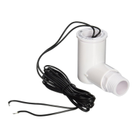
MODEL SS2 LOW VOLTAGE CONDENSATE OVERFLOW SHUTOFF SWITCH
Safe-T-Switch Model SS2
INSTALLATION:
NOTICE: Failure to read and comply with all warnings, cautions and instructions prior to starting installation may
cause personal injury and/or property damage and void the warranty.
AUXILIARY DRAIN OUTLET INSTALLATION:
1. Disconnect power to unit at main panel and glue ¾” stub onto drain pan outlet adapter.
2. Ensure switch assembly is inserted into 1” inlet of PVC elbow so that float stem is at inside (bottom) of switch elbow. Float stem can be adjusted
by threading it out of plug assembly. DO NOT GLUE.
3. Plumb ¾” inlet of PVC elbow to stub as close to drain outlet as possible, ensuring that stub does not interfere with switch float. Position switch
level with or below outlet. Switch may be angled up to 20° by rotating it on stub.
4. Wire switch as instructed under Wiring, below.
5. Test all fittings/connections for plumbing leaks.
6. Test switch by liting float with unit running. Unit should stop running if correctly wired.
7. Test switch sensitivity: Plug drain downstream from installation point and run unit to fill pan. Float should rise and unit should stop before pan
overflows. If the pan overflows, check that the float stem is at the inside bottom of the elbow and, if necessary, reposition entire assembly so that
switch is below or angled down from the pan outlet.
8. Ax warning sticker on air handler or condenser unit.
INLINE INSTALLATION FOR (WALL) UNITS WITH VERTICAL DRAIN OUTLETS (see Fig. 1)
NOTE: It is recommended that this device be installed on the primary drain line between the pan outlet and P-Trap on wall units with vertical drain
outlets (such as First Company® and Janitrol®). This will prevent the switch from shutting o the fan coil or activating the alarm circuit in the event
condensate drips directly from the coil into the auxiliary pan outlet when the coil becomes dirty.
1. Disconnect power to unit at main panel and glue 5” stub down from the primary pan outlet.
2. Glue ¾” Tee to bottom of stub with Tee stem horizontal & plumb.
3. Glue ¾” stub into horizontal outlet of Tee, ensuring it is also plumb.
4. Ensure switch/plug assembly is inserted into 1” inlet of PVC elbow so that float stem is at inside (bottom) of switch elbow. Float stem can be
adjusted by threading it out of plug assembly. DO NOT GLUE.
5. Glue drain line with P-Trap onto remaining outlet of Tee.
6. Wire switch as directed under Wiring, below.
7. Test switch by liting float with unit running. Unit should stop running if correctly wired.
8. Test all fittings and connections for plumbing leaks.
9. Ax warning sticker on air handler or condenser unit.
Figure 1: Vertical Drain Outlet Installation
Typical Wall Unit
View upward from bottom and back of unit
3.25” Minimum space required to
remove oat switch
Figure 2: Horizontal Ceiling (“Pancake”) Units