Page 2 of 3
IMPORTANT SAFETY INFORMATION:
1. This device must be installed strictly in accordance with manufacturer’s instructions (to ensure proper operation) and in accordance
with all applicable local plumbing, drainage and electrical codes.
2. Electric shock hazard. Disconnect power supply before installing this product to avoid electrical shock and/ or equipment damage.
UseinClass2(thermostat)circuitonly,nottoexceed24-volts,1.25ampstoavoiddamageorrehazard.
1. This device will not detect clogs occurring upstream from the installation point.
2. If not present, it is recommended that a fuse and time delay be installed, to protect the 24-volt circuit and avoid rapid cycling of equipment,
prior to installing this product.
3. Thisproductisintendedforuseinwateronly.Notforuseinthepresenceofammableliquidsorvapors.
4. Refer to the appropriate HVAC equipment operation manual prior to installing this product.
5. Do not use on dual compressor systems.
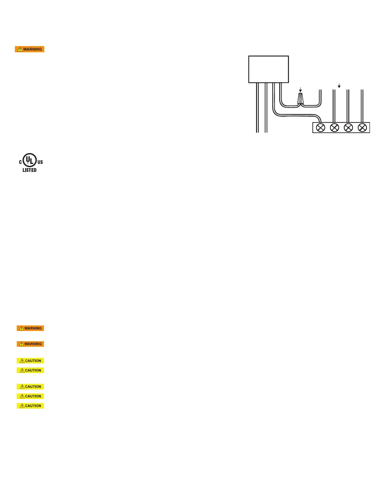
WIRING
1. Disconnect power to unit at main panel prior to performing electrical work. 2. If not
present, it is recommended that an inline fuse be installed to protect the 24-volt circuit. 3. Connect
"power" (black) wires to 24 VAC power supply terminal. 4. Locate the 24-volt thermostat cable
entering the air handler unit. 5. Disconnect or cut the red wire and connect to "common" (gray)
switch lead using wire nut. Connect "NC" (purple) switch lead to air handler terminal. Incorporating
switch in red circuit shuts down entire unit. If placed in the yellow circuit, fan continues to run
(inhibits mold during long absences).
*This is general wiring instruction for Normally Closed (NC) cirucuits. For Normally Open (NO)
switching, use "Common" (gray) and "NO" (orange) switch leads. Read air handler installation
manual for the shut-off signal type (i.e. NC or NO) and signal terminal locations.
Note: The CPU is plenum rated but the lead is not and must remain outside of plenum
space!
MAINTENANCE
TESTING: (Turn on power to A/C unit)
SWITCH:
1. Once installed and the power is turned on, CPU will display a green LED. If the green LED does not come on, check the "Power" (black) wire
connection and voltage. 2. Test the switch by shorting across the probes with wet finger, a metallic conductor or water. If wired correctly, the unit
will stop and the red LED will come on after about 5 seconds. When released, after about 5 seconds the red LED will go off, the green and amber
LEDs will come on and the A/C unit will restart. The amber LED will be turned off automatically in about 4 days. To turn off amber LED manually,
see reset instruction tag on probe wire.
SENSOR POSITION:
3. Test the sensor position: Test the sensor position by turning on the A/C unit to produce a normal condensate flow. If the sensor is too low, the
switch will activate and shut down the unit. Next, block the drain to allow the pan to fill with water. The switch should activate before the pan
overflows. If necessary, adjust the sensor as described above.
SPECIFICATIONS
24 VAC, 5 Amp. Switching Capacity, Class 2, 12”, 18 AWG Lead Wires, 72” plenum rated tail.
IND. CONT. EQ.
25XE
UL 508
UL 2043
Switch
24V Power Supply
NC
Common
Red
Yellow
Green
White
From Thermostat
Wire Nut
Figure 2: Wiring Diagram for Unit Shutdown
SAFE-T-SWITCH
®
SS500EP
For primary drain pan
 Loading...