Series 1000 and 1500
44
26.2. When properly adjusted, the brake should do
two things: it should stop and hold the tractor
when applied, and it should not drag when
released.
26.3. To check that the brakes hold the tractor:
• Open the relief valve.
• Set the parking brake.
• Attempt to push the tractor.
• The wheels should skid without rotating.
• If the brakes do not hold the tractor, the adjust-
ment needs to be tightened or the brakes need
to be repaired.
26.4. To check that the brakes do not drag:
• Open the relief valve.
• Release the parking brake.
• Attempt to push the tractor - it should move with
about 40 lbs of force. More force indicates drag.
• If the brakes drag, they need to be adjusted or
repaired.
26.5. There is no linkage adjustment. All adjustment is
done at the brake caliper.
26.6. To reach the brake caliper, lift and safely support
the right rear corner of the tractor.
26.7. Remove the right rear wheel of the tractor using
a 3/4” wrench.
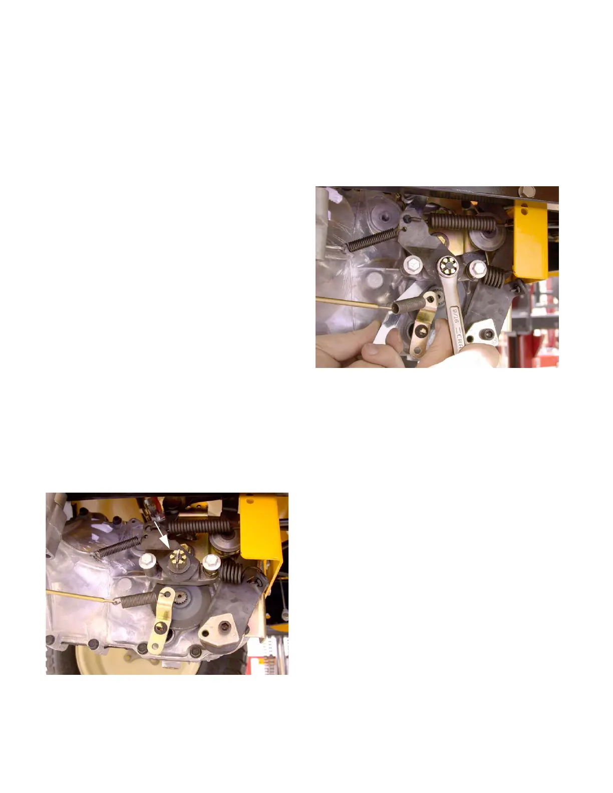
26.8. Hydro-Gear transaxles use a castle nut locked
with a cotter pin.
See Figure 26.8.
26.9. Insert a .015” feeler gauge between the brake
rotor and the outer brake pad. There should be
slight drag on the feeler gauge.
26.10.If the feeler gauge is too loose, or will not go in,
brake caliper adjustment is necessary.
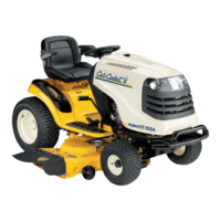
26.11. Remove and discard the cotter pin. A 9/16”
wrench will turn the adjustment nut.
See Figure
26.11.
26.12.Tighten the nut to reduce the clearance. Loosen
the nut to increase the clearance.
26.13.Check the movement of the brake arm:
• The brake arm should move forward as the
brake is applied.
• The return spring should draw the brake arm
back against the spacer when the brakes are
released.
26.14.Visually check the thickness of the brake pads:
they are visible within the caliper.
26.15.Check the brake rotor:
• Confirm that the brake rotor floats on the splined
shaft by sliding it in and out with light finger pres-
sure.
• If it binds on the shaft it may cause brake drag
and reduced holding performance.
• A rotor that has been dragging will frequently be
discolored by the heat (blue).
Figure 26.8
Castle nut
Figure 26.11
 Loading...