6
3
Shipping Brace Removal
WARNING: Make sure the
lawnmower’s engine is off.
Remove the ignition key before
removing the shipping brace.
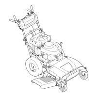
• Locatetheshippingbrace,ifpresent,foundonthe
rightsideofthecuttingdeck.SeeFigure3-1.
• Whileholdingthedischargechutewithyourleft
hand,removetheshippingbracewithyourright
handbygraspingitbetweenyourthumbandindex
fingerandrotatingitclockwise.
WARNING: The shipping brace,
used for packaging purposes
only, must be removed and
discarded before operating your
lawnmower.
WARNING: The mowing deck
is capable of throwing objects.
Failure to operate the mower
without the discharge cover in
the proper operating position
could result in serious personal
injury and/or property damage.
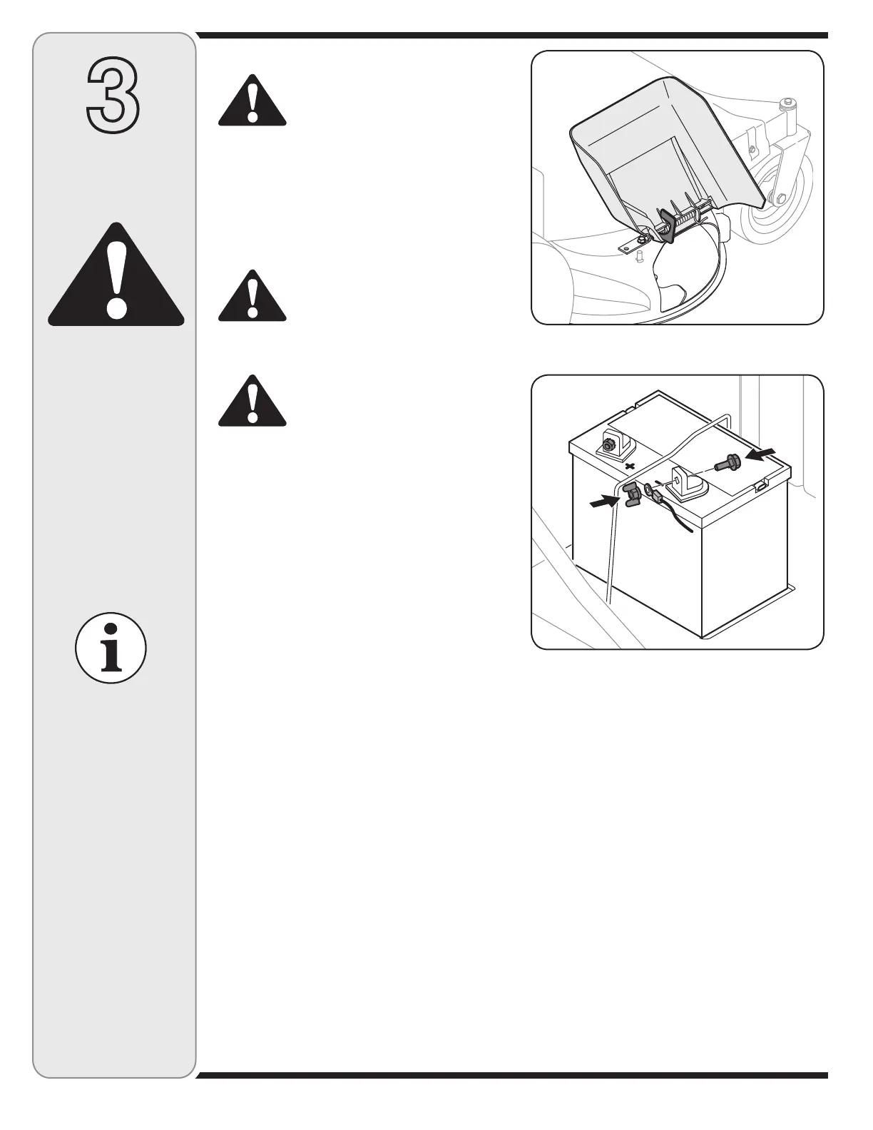
Attaching the Negative Battery
Cable
NOTE:ThepositivebatteryterminalismarkedPos.(+).
ThenegativebatteryterminalismarkedNeg.(–).
Thepositivecable(heavyredwire)issecuredtothe
positivebatteryterminal(+)withahexboltandhexnut
atthefactory.
Thenegativecable(heavyblackwire)maybesecured
tothenegativebatteryteminalatthefactory.Ifithasnot
beenattached,proceedasfollows:
• Removethehexboltandwingnut(hexnut)fromthe
negativecable.
• Removetheblackplasticcover,ifpresent,fromthe
negativebatteryterminalandattachthenegative
cable(heavyblackwire)tothenegativebattery
terminal(–)withtheboltandnut.SeeFigure3-2.
• Makecertaintheretainingrodisinpositionoverthe
battery,securingitinplaceandmakesurethered
rubberbootcoversthepositivebatteryterminalto
helpprotectitformcorrosion.SeeFigure3-1.
NOTE:Ifthebatteryisputintoserviceafterthedate
shownonthebattery,chargethebatteryasinstructed
intheMaintenanceSectionofthismanualpriorto
operatingtheunit.
Figure 3-2
Figure 3-1
Disconnect and
ground the spark
plug wire as instruct-
ed in the separate
engine manual.
IMPORTANT
This unit is shipped
WITHOUT GASOLINE
or OIL. After assem-
bly, service engine
with gasoline and
oil as instructed in
the separate engine
manual packed with
your unit.
Assembly
and Set-Up
WARNING
Unfolding the Handle
1. Removethestarknobsandcarriagescrewsfromthe
lowerhandle.SeeFigure3-3.
2. Pivottheupperhandleintooperatingposition.Be
carefulnottocrimpcables.SeeFigure3-4.
3. Reinstallthecarriagescrewsandknobsremoved
earlier.
4. Tightentheupperandlowerstarknobsandcarriage
screwstosecuretheupperhandletothelower
handle.SeeFigure3-4.
5. Thehandleheightcanbeadjustedtoanyofthree
positions.Forinstructions,refertoHandleHeightinthe
MaintenanceandAdjustmentssectionofthismanual.

 Loading...