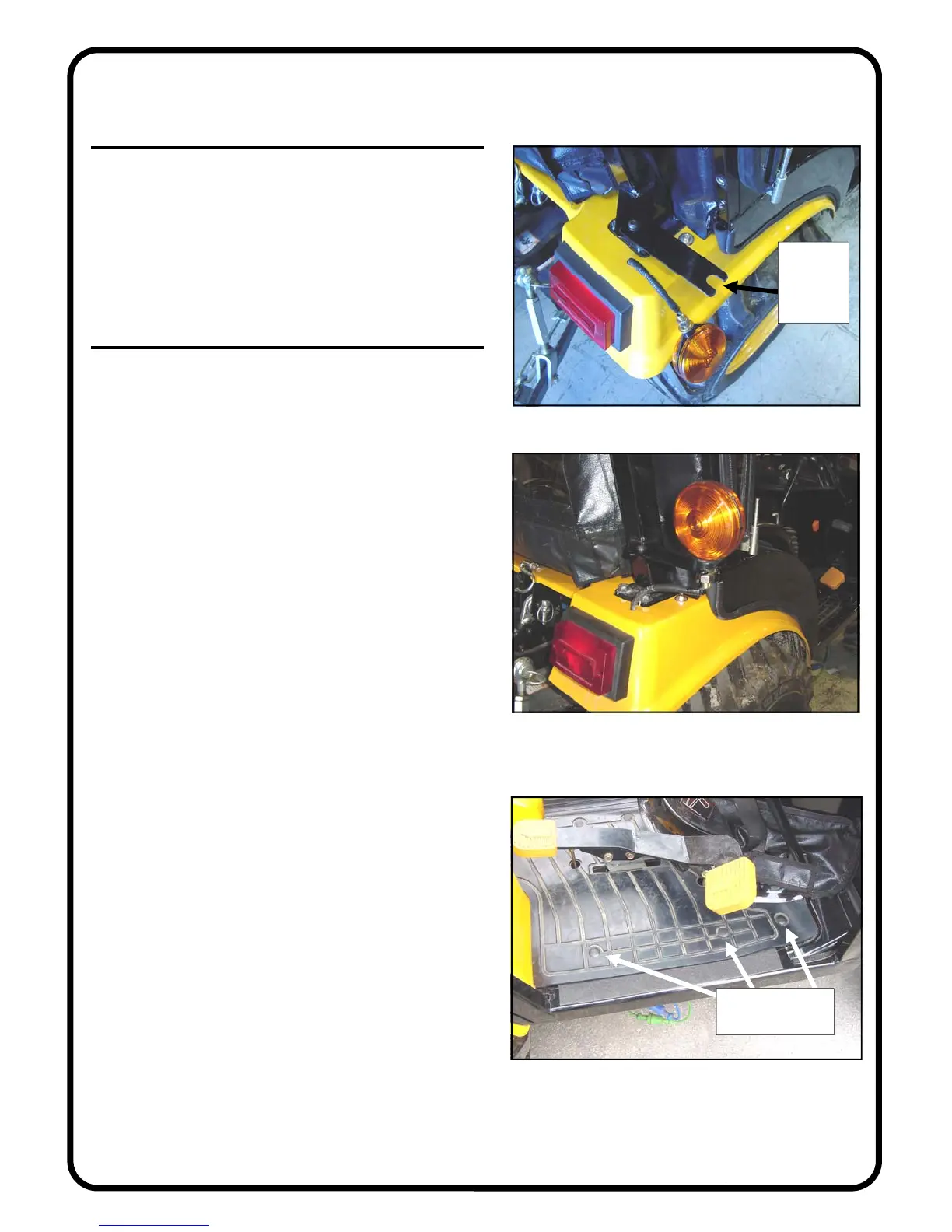
17. FLASHER LIGHT BRACKET
17.1 Per fig. 17.1, install the flasher light brackets using
the following hardware per side of the tractor: one 5/16-18 x
3/4” long button head bolt, two steel washers, and one lock-
nut. Repeat for the opposite side. Tighten the bolts.
17.2 Per fig. 17.2, re-install the flasher light. Note: both
washers (flat and lock) to be on the bottom side of the
bracket along with the hex nut.
18. FINISHING TOUCHES
18.1 Install the gas shock to the frame and door with the
small piston end towards the door. Press the button on the
compression fastener to lock the gas shock to the ball stud.
18.2 Install the supplied 5/16” nut covers (qty.: 16) on the
interior hex locknuts by snapping over nut. Install the two
1/4” nut covers on the locknuts for the vibration mounts.
18.3 Install six (6) new plastic pine tree clips (3 per side)
through the rubber floor mats. Press in place by hand.
Rev. -, p. 16 of 19
Fig. 18.3 (view from right side of tractor)
Fig. 17.1 (view from right side of tractor)
Fig. 17.2 (view from right side of tractor)
open
ended
slot to be
outboard
install 3 pine tree
clips per side
 Loading...