2-2
Step 6. Attach DRAIN LINE to DRAIN LINE FITTING. To
prevent back pressure from reducing flow rate
below minimum required for backwash, DRAIN
LINE MUST be sized according to run length and
relative height. Be careful not to bend flexible drain
tubing sharply enough to cause "kinking" (if kinking
occurs DRAIN LINE MUST BE REPLACED). Typi-
cal examples of proper DRAIN LINE diameters are:
(1) 1/2 in. ID up to 15 ft. when discharge is lower
than INLET.
(2) 5/8 in. ID up to 15 ft. when discharge is slightly
higher than INLET.
(3) 3/4 in. ID when drain is 25 ft. away and/or drain
is installed overhead.
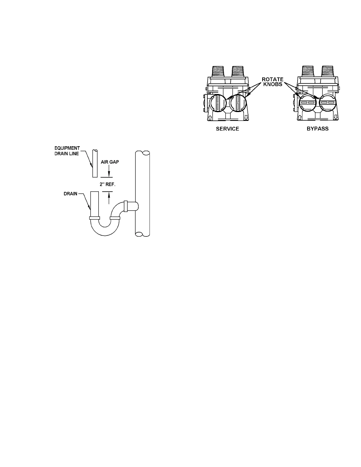
Figure 3. TYPICAL DRAIN
Step 7. Position DRAIN LINE over drain and secure firmly.
To prevent backsiphoning of waste water, provide
an air gap of at least 2 in. or 2 pipe diameters
between end of drain hose and drain (Figure 3). DO
NOT raise DRAIN LINE more than 10 ft. above floor.
Step 8. Connect one end of the 3/8 in. poly line to BRINE
VALVE located on the right side of CONTROL
VALVE. Connect other end to ELBOW inside of
BRINE WELL. Brass insert sleeves and plastic
ferrules must be used where necessary. (Figure 2
and CONTROL VALVE PARTS Drawing, Section
6).
Step 9. Install OVERFLOW LINE to brine tank OVERFLOW
FITTING (Figure 2). Discharge of line must be lower
than OVERFLOW FITTING. DO NOT INTERCON-
NECT OVERFLOW LINE WITH VALVE DRAIN
LINE.
Step 10. Make certain BYPASS VALVE INLET and OUT-
LET KNOBS ARE IN "BYPASS" position. After all
plumbing connections have been completed, open
main water shut-off valve or restore power to well
pump. Check for leaks and correct as necessary.
Figure 4. BYPASS VALVE
Step 11. Manually stage control to BACKWASH POSI-
TION by turning "MANUAL REGENERATION
KNOB", clockwise to "BACKWASH" position, re-
fer to HOW TO SET TIME CLOCK REGENERA-
TION CONTROL (Section 3).
Step 12. Partially open INLET valve in plumbing or on
BYPASS VALVE (Figure 4). This will allow the
unit to fill slowly from the bottom up, eliminating air
entrapment. Allow unit to fill slowly, failure to do
so could result in loss of resin to the drain. Once
a steady stream of water, no air, is flowing to drain,
the INLET VALVE can be fully opened. The
OUTLET valve can also be opened and the BY-
PASS (if applicable) can be closed. Manually
advance control to SERVICE POSITION. Plug
into a non-switched 110/120V, 60Hz power source.
Step 13. On time clock initiated models, set REGENERA-
TION FREQUENCY. Refer to REGENERATION
FREQUENCY SCHEDULES (Section 3) to deter-
mine correct frequency, then refer to HOW TO
SET TIME CLOCK REGENERATION CONTROL
(Section 3) for instructions on setting frequency.
For meter initiated models, refer to HOW TO SET
METER REGENERATION CONTROL.
NOTE: Regeneration settings for both time clock
and meter initiated models are factory preset for
the most efficient salt use and minimum water
consumption used for regeneration (as little as 50
gallons), and conform to the INDUSTRY SALT
EFFICIENCY STANDARDS (required by some
states). REGENERATION FREQUENCY
SCHEDULES are designed for use with factory
regeneration settings (listed in SPECIFICATIONS
AND OPERATING DATA, Section 5).
 Loading...