EasyManua.ls Logo

Cynosure Cynergy User Manual

Cynosure Cynergy
79 pages
To Next Page IconTo Next Page
Page #1 background imageLoading...
Page #1 background image
Cynergy
850-1065-000, Rev. 6
OPERATOR MANUAL
CYNOSURE
®
5 Carlisle Road, Westford, MA, 01886, USA
Phone: 978-256-4200 www.cynosurelaser.com

Table of Contents

Other manuals for Cynosure Cynergy

Questions and Answers:

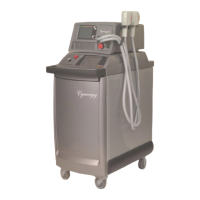
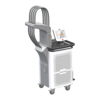
Cynosure Cynergy Specifications

General IconGeneral
Wavelength585 nm (Pulsed Dye), 1064 nm (Nd:YAG)
Laser TypePulsed Dye and Nd:YAG
Spot Size2 mm, 3 mm, 5 mm, 7 mm, 10 mm
Fluence5 - 600 J/cm² (Nd:YAG)
Electrical Requirements200-240 VAC, 50/60 Hz
DisplayTouchscreen
Energy OutputPulsed Dye: Up to 20 Joules, Nd:YAG: Up to 60 Joules
Cooling SystemIntegrated Dynamic Cooling Device (DCD)

Summary

Glossary of Symbols and Abbreviations

Symbols and Abbreviations Explained

Provides definitions for symbols and abbreviations used in the manual.

Section 1 Introduction

About the Lasers

Description of the Cynergy laser's dual-wavelength technology and principles.

About the Manual

Details the content and purpose of the operator's manual.

Section 2 Equipment Safety

Optical Hazard

Details risks of eye damage from laser radiation and necessary precautions.

Electrical Hazard

Highlights high voltage risks and precautions for operating the laser system.

Chemical Hazard

Discusses safe handling of dye medium and precautions against spills.

Potential Chemical Accidents and Responses

Provides emergency response guidelines for chemical exposure incidents.

Hot Water Hazard

Warns about the risk of scalding from hot cooling water and precautions.

Laser-Induced Fire Hazard

Outlines precautions to prevent fires caused by laser energy interaction.

Electromagnetic Compatibility Hazards

Addresses potential interference issues with RF equipment and EMC precautions.

Laser Safety Features

Explains built-in safety mechanisms to prevent misuse and accidental activation.

Key Switch

Describes the function of the key switch for controlling laser activation.

Emergency Laser Stop

Details the emergency stop function for immediate laser shutdown.

Standby Mode

Explains the standby mode to prevent unintentional laser activation.

Delayed Ready Mode

Describes the safety delay before laser activation for operator preparation.

Automatic Shutdown Feature

Covers automatic system shutdown due to faults and fault code display.

Remote Interlock

Explains the remote interlock feature for safety in treatment rooms.

Audible Tone

Indicates laser emission with a pulsed tone.

Laser Warning Sign

Recommends posting warning signs at treatment room entrances.

Locking Casters

Details how to lock and unlock the laser system's casters.

Device Labels

Identifies and explains the purpose of safety labels on the laser device.

Figure 1A-Device Labels in Position

Diagram showing the physical placement of device labels on the laser.

Figure 1B-Device Labels Used

Illustrations and descriptions of various safety labels affixed to the laser.

Section 3 Site Preparation

Spatial Requirements

Specifies the physical dimensions and weight of the Cynergy laser system.

Electrical Requirements

Details the power supply, voltage, and amperage needed for the laser.

Environmental Requirements

Outlines conditions for air quality, humidity, and temperature for optimal operation.

Storage and Transport Requirements

Provides guidelines for safe storage and transportation of the laser system.

Equipment Disposal

Instructs on the proper disposal of laser equipment according to WEEE directive.

Section 4 Laser Description

Main Components

Identifies the primary physical parts of the Cynergy laser system.

Figure 2A-Main Components, Front

Illustration of the front view showing key components of the laser.

Figure 2B-Main Components, Inside Front Door

Diagram showing internal components accessible via the front door.

Figure 2C-Main Components, Rear View

Illustration of the rear view detailing system connections and ports.

Figure 2D-Main Components, Right Side from Rear

Diagram of the laser's right side, highlighting components like fans and cord holders.

Key Switch

Explains the operation and function of the system's key switch.

Handpieces and Delivery Optical Fiber

Describes the optical fiber and handpiece system used for laser delivery.

Connecting the Optical Fiber

Step-by-step instructions for connecting the optical fiber to the laser system.

Changing Handpieces

Procedure for safely replacing the handpiece and recalibrating the system.

Figure 3-Handpiece

Diagram illustrating the handpiece, its components, and connections.

Trigger Switches

Details the finger switch and foot switch used to activate the laser.

Front Control Panel

Overview of the controls and displays on the laser's front panel.

Figure 4-Front Control Panel

Image labeling the main controls on the front panel.

Emergency Laser Stop

Explains the emergency stop button for immediate system shutdown.

Cal Port

Describes the calibration port and its function in measuring laser energy.

Display

Details the touch screen display used for system interaction and monitoring.

Display Screens

Explains the various screens and interfaces of the laser's software.

Home Screen

Description of the initial screen after system startup and its navigation options.

Figure 5A-Home Screen

Visual representation of the Home Screen interface.

Treatment Screens

Details the screens used for setting treatment parameters like fluence and pulse width.

Figure 5B-PDL Screen

Example screen for setting PDL treatment parameters.

Figure 5C-YAG Screen

Example screen for setting YAG treatment parameters.

Treatment Screen Elements

Breaks down the components and functions of the treatment display screens.

Figure 5D-Laser Screen Elements

Diagram labeling specific elements within the treatment screens.

MultiPlex Treatment Screen

Explains the interface for the MultiPlex option, combining PDL and YAG.

Figure 5E-MultiPlex Laser Screen

Illustration of the MultiPlex treatment screen.

Utility Screen

Describes the utility screen for diagnostic information and system controls.

Figure 5F-Utility Screen

Diagram of the Utility Screen interface with its various options.

Option Screen

Details the options available for system configuration and language settings.

Figure 5G-Option Screen

Visual representation of the Option Screen.

System Specifications

Provides technical specifications for the Cynergy laser system.

General Specifications

Lists general technical data for the Cynergy laser, including dimensions and power.

Fluence Specifications

Details fluence parameters for PDL and YAG laser operations.

Section 5 Laser Operation

Laser Start-Up

Step-by-step guide for powering on and preparing the laser system.

Laser Shutdown

Procedure for safely turning off the laser system.

Laser Calibration

Procedure for calibrating the laser's energy output before use.

Energy Regulation During Treatment

Explains how the system maintains energy output and handles 'Out of Range' faults.

Laser Operation

Guidance on selecting parameters and delivering laser pulses during treatment.

Changing Treatment Parameters

Procedure for safely adjusting treatment parameters during operation.

Section 6 Clinical Application-YAG

YAG Operator Training Requirements

Specifies essential training aspects for YAG laser operators.

YAG Indications, Contraindications, Adverse Effects

Lists conditions treated, patient restrictions, and potential adverse effects for YAG laser.

YAG Pretreatment Recommendations

Steps for patient assessment, information, and preparation before YAG treatment.

YAG Treatment Recommendations

Guidelines for setting energy levels, number of sessions for YAG treatment.

YAG Posttreatment Recommendations

Patient care instructions after YAG laser treatment.

Section 7 Clinical Application-PDL

PDL Operator Training Requirements

Specifies essential training aspects for PDL laser operators.

PDL Indications, Contraindications, Adverse Effects

Lists conditions treated, patient restrictions, and potential adverse effects for PDL laser.

PDL Patient Selection

Identifies ideal patient candidates for PDL laser treatment.

PDL Pretreatment Recommendations

Steps for patient assessment, information, and preparation before PDL treatment.

PDL Treatment Recommendations

Guidelines for setting energy levels, number of sessions for PDL treatment.

PDL Posttreatment Recommendations

Patient care instructions after PDL laser treatment.

Section 8 Clinical Application–MultiPlex Option

MultiPlex Operator Training Requirements

Specifies essential training aspects for MultiPlex option operators.

MultiPlex Indications, Contraindications, Adverse Effects

Lists conditions treated, patient restrictions, and potential adverse effects for MultiPlex.

MultiPlex Patient Selection

Identifies ideal patient candidates for MultiPlex option treatment.

MultiPlex Pretreatment Recommendations

Steps for patient assessment, information, and preparation for MultiPlex treatment.

MultiPlex Treatment Recommendations

Guidelines for setting parameters, sessions for MultiPlex treatment.

MultiPlex Posttreatment Recommendations

Patient care instructions after MultiPlex laser treatment.

Section 9 Maintenance

Cleaning and Disinfecting Equipment

Guidelines for cleaning and disinfecting the laser system and handpiece.

Water Reservoir Maintenance

Instructions for refilling the laser's water reservoir with distilled water.

Dye Kit Methodology and Injection

Explains the function of the dye filter and inject bottle in dye laser operation.

Replacing the Dye Kit

Step-by-step guide for replacing the dye filter and inject bottle.

Troubleshooting and Fault Codes

Information on identifying and resolving common laser system faults.

Troubleshooting Chart

A guide to diagnosing and solving common laser operational problems.

Transferring Diagnostic Data

Instructions for downloading diagnostic data to a USB stick for analysis.

Section 10 Customer Support

Warranty Information

Details warranty information for direct and distributor purchases.

Warranty Claims Procedure

Procedure for filing claims for damaged or defective merchandise.

Installation and Training

Describes the process of laser installation and initial customer training.

Customer Service Contact

Provides contact information and hours for technical and clinical support.

Appendix A Service Calibration

Calibration Schedule and Overview

Explains the built-in energy meter and its components for calibration.

Required Equipment for Calibration

Lists the necessary equipment for performing laser calibration.

Calibration Procedures

General steps and prerequisites for calibrating the laser system.

Appendix B Electromagnetic Compatibility

Electromagnetic Emissions Guidance

Specifies emissions compliance and guidance for the electromagnetic environment.

Electromagnetic Immunity Guidance

Details immunity test levels and guidance for the electromagnetic environment.

Appendix C Declaration of Conformity

Related product manuals