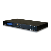
10
tree. Otherwise, in routing mode, this button allows you to make your
input source selection.
-/OUT: Within the menu, this button moves you down within the
menu tree. Otherwise, this button starts routing mode and allows you
to begin your output destination selections.
8
PRESET: Press this button to recall saved presets. A maximum of 8
presets can be stored in the unit. Presets are created and stored via the
WebGUI. Please refer to section 6.10.1 for advanced preset settings.
9
LOCK: Press and hold this button for 3 seconds to lock/unlock all
buttons on the front panel. The OLED will display an “L” in the upper
right corner to indicate the front panel is locked.
10
OLED WINDOW: Displays the unit’s menu, settings and information.
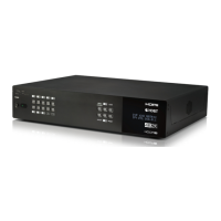
6.2 Rear Panel
CAT5e/6 OUT
HDMI IN HDMI IN HDMI IN HDMI IN HDMI IN HDMI IN
IR IN
IR OUTIR OUTIR OUTIR OUTIR OUTIR OUT
1 2
A
RS-232 POH 24V
CAT5e/6 OUT
IR IN
B
3
CAT5e/6 OUT
IR IN
C
4
CAT5e/6 OUT
IR IN
D
5
CAT5e/6 OUT
IR IN
E
6
CAT5e/6 OUT
IR IN
F
MAIN 24V
SERVICE
B
A
D
C
F
E
2
1
2
1
1
CAT5e/6 OUT
HDMI IN HDMI IN HDMI IN HDMI IN HDMI IN HDMI IN
IR IN
IR OUTIR OUTIR OUTIR OUTIR OUTIR OUT
1 2
A
ZONE
ANALOG
DIGITAL
ALLCONTROL RS-232
CAT5e/6 OUT
IR IN
B
3
CAT5e/6 OUT
IR IN
C
4
CAT5e/6 OUT
IR IN
D
5
CAT5e/6 OUT
IR IN
E
6
CAT5e/6 OUT
IR IN
F
HDMI OUTHDMI OUT MAIN 24V
SERVICE
IR IN IR OUT
G
H
B
A
L
R
L
R
D
C
F
E
2
1
2
1
1
AUDIO OUT
AUDIO OUT
AUDIO IN
1
2
3
4
V+
GND
GND
GND
V+
L
R
L
R
EXTENDED
AUDIO IN
2
6 7 8 9 10 11
1 2 3 4 5 12 13
1
HDMI IN & IR OUT 1~6: Connect up to 6 source devices to the HDMI
ports using appropriate quality HDMI cables. Input source devices
include Blu-ray players, set-top boxes, game systems and so on. These
inputs are DVI-D compliant (with the use of DVI to HDMI adapters or
cables). Attach IR blasters to the IR Out ports to transmit the IR signals
received from connected HDBaseT Receivers. The IR signal routing
follows the HDMI signal routing.
Note: The use of “Premium High Speed HDMI” cables is highly
recommended.
2
CAT5e/6 OUT & IR IN A~F: Connect the Cat.5e/6 outputs via an
appropriate cable to the input ports of compatible HDBaseT receivers
for HDMI audio/video and IR/RS-232 control signal transmission. In
order for an IR signal to be transmitted along with the HDMI signal an
IR extender must be connected to the associated IR In port. IR signals
coming back from the connected HDBaseT receiver can be used to
 Loading...