9
6. OPERATION CONTROLS AND FUNCTIONS
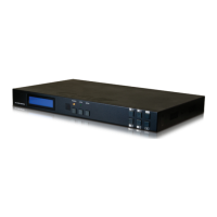
6.1 Front Panel
POWER
ENTER
PRESET
MENU
/CANCEL
LOCK
A
1
B
2
C
3
D
4
E
5
F
6
G
7
H
8
9
10
+
IN
-
OUT
1
POWER: Press this button to power the unit on or place it into stand-
by mode.
Note: Network functionality and PoH (if the second power supply is
connected) remain active when the unit is in stand-by mode.
2
POWER LED: This LED will illuminate GREEN to indicate the unit is on
and receiving power. When the unit is in stand-by mode the LED will
illuminate RED.
3
IR WINDOW: Accepts IR signals from the included IR remote for
control of this unit only.
4
OUTPUT A~H & INPUT/NUMBER 1~6: Press the “OUT” button to
enter output selection mode. Next, press the output keys (A~H) of
the outputs you wish to route a source to (they will ash to indicate
selection). Next, press the “IN” key followed by the input (1~6) you
wish to route to the selected outputs. Finally, press “ENTER” to conrm
your selection and execute the routing change.
For example, if you wish to display input 1 on outputs A~D then the
following sequence of button presses should be performed: OUT
→
A,
B, C, D
→
IN
→
1
→
ENTER
When directly entering Ethernet address information into the unit all
10 buttons are used to represent the numbers from 0 to 9 (button 10
= 0) to make number entry more streamlined.
5
MENU/CANCEL: Press the “MENU/CANCEL” button to enter the OLED
menu, or to back out from menu items. For a description of the menu
tree, please refer to section 6.5.
6
ENTER: Press this button to conrm selections.
7
+/IN: Within the menu, this button moves you up within the menu
 Loading...