190
Installation
Unloader valve and relief valve are
mounted in an uprght position, with
exhaust port3 pointing downwards.
The total volume of air supplied by
the compressor must be allocated to
two 18Ŧ1.5 pipelines, one line being
connected to port 1 of the unloader
valve and the other one to port 1 of
the relief valve(see installation dia-
gram). The pipelines should have a
length of approx. 2m each(if neces-
sary, to be coiled) and must be laid
in such a manner that the tempera-
ture at ports 1 of both the unloader
valve and the relief valve does not
exceed 150°C.
For the control line from port 23 of
the unloader valve to port 4 of the
relief valve use either a pressure/tem-
perature–resistant hose with an inside
diameter of 6mm, with fitting to suit
dimensions as shown in drawing I, or
a 6Ŧ1 pipe with connection to suit
dimensional drawing II. In both cases
a maximum length of 1 m should not
be exceeded.
The pressure relief noise generated in
the cut–out phase is reduced by
means of hoses attached to the
exhaust connections 3 of both the
unloader valve and the relief
valve ; this can also serve to drain off
any oil that may have been separat-
ed.
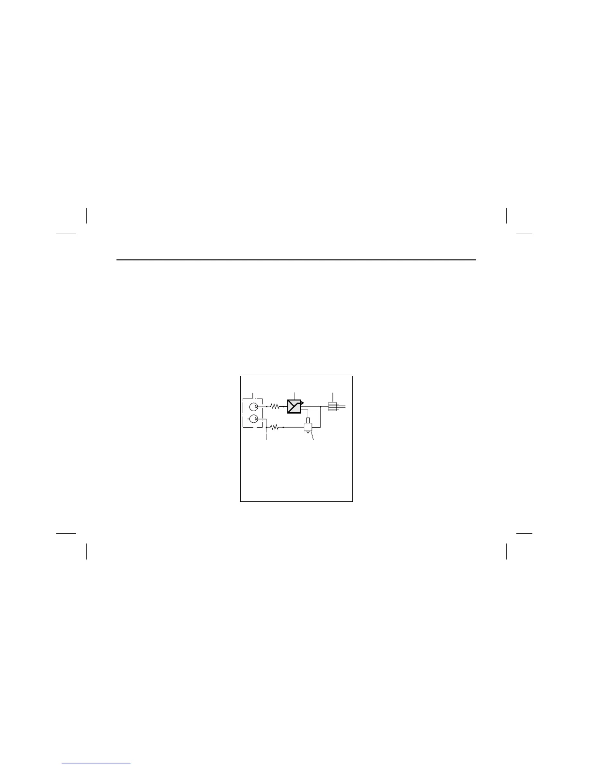
Installation diagram


 To Next Page
 Loading...