1) Cut J18 on M-PCB, then temp. is lowered -2 than [Mid OFF point].
2) In addition to 1) action, cut J22 on M-PCB, then the temp. is lowered -1 more.
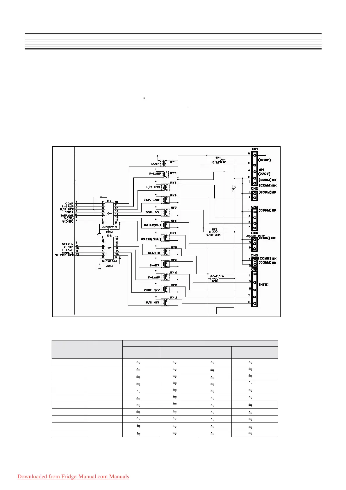
Relay Function
Circuit Diagram
How it works ;
ON Condition OFF Condition
Control
Control
Method
MICOM
PORT
IC 2 Output
PIN
MICOM
PORT
IC03 Output PIN
COMP REPLAY
REPLAY
REPLAY
REPLAY
REPLAY
REPLAY
REPLAY
REPLAY
REPLAY
REPLAY
REPLAY
#1 3.7V #10 0.7V #1 0V #10 12V
R-LAMP
#4 3.7V #11 0.7V #4 0V #11 12V
DIS-LAMP
#3 3.7V #12 0.7V #3 0V #12 12V
DISP-SOL
#5 3.7V #13 0.7V #5 0V #13 12V
WATER(ICE)
#1 3.7V #10 0.7V #1 0V #10 12V
WATER(DIS)
#4 3.7V #11 0.7V #4 0V #11 12V
GEAR-M
#3 3.7V #12 0.7V #3 0V #12 12V
D-HTR
#5 3.7V #13 0.7V #5 0V #13 12V
F-LAMP
#4 3.7V #11 0.7V #4 0V #11 12V
CUBE-SOL
#4 3.7V #11 0.7V #4 0V #11 12V
W /S HTR
#2 3.7V #14 0.7V #2 0V #14 12V
C
C
* In case refrigeration of refrigerator compartment is poor or insufficient though comp. and R-fan
operate in normal way ;