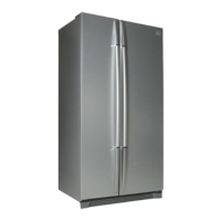
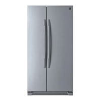
Do you have a question about the Daewoo FRS(N)-U20IA and is the answer not in the manual?
Precautions against electric shock, proper grounding, and handling of power cords.
Safety rules for using the refrigerator, including storage of flammable materials and handling glass bottles.
Safety measures to take when scrapping the refrigerator, especially concerning children.
Detailed measurements of the refrigerator for installation planning and space assessment.
Labels and identification of parts within the freezer and refrigerator compartments.
Comprehensive technical data including volume, weight, dimensions, and component specifications.
Specifications for sensors, heaters, electrical parts, and refrigerant types used in different models.
Explains the display interface and how to adjust temperature settings for freezer and refrigerator compartments.
Details the automatic defrosting cycle, including its stages and initiation conditions.
Procedures for forced defrost, fan voltage control, and other operational modes.
Covers controls for louvers, alarms, interior lights, demonstration mode, and sensor compensation.
Illustrates the electrical power flow and component connections within the refrigerator's circuit.
Details the role and operating characteristics of temperature sensors (F, R, D).
Explains relay operations and fan motor control principles for different models.
Provides detailed wiring schematics for different refrigerator models.
Shows the detailed circuit layout of the main control board for troubleshooting.
Illustrates the physical placement of key components inside and outside the refrigerator.
Procedure for disassembling and checking the resistance of the ice maker tube assembly.
Steps for disassembling and testing the geared motor, solenoid valve, and micro switch.
Details on checking Main PCB components and ice maker parts like sensors and motors.
Troubleshooting steps for when the refrigerator fails to start or lights are off.
Diagnosis for freezing failures, including checking components like compressor, heaters, and sensors.
Troubleshooting steps for refrigeration failures, checking motors, sensors, and gaskets.
Guides for diagnosing and resolving operational noises from the compressor, refrigerant flow, fans, and pipes.
Steps to resolve issues where the door opening alarm continues despite the door being closed.
Overview of the steps involved in heavy repair, including tools and contents for each process.
Important safety and procedural precautions to follow during refrigerant and cooling cycle repairs.
Detailed practical steps for residual refrigerant removal, nitrogen blowing, and vacuum degassing.
Essential regulations and safety guidelines to adhere to during refrigerant handling and repair work.
Illustrates welding points and the flow of the refrigeration cycle for brazing procedures.
Guidance on checking dimensions, finding a suitable location, and preparing for installation.
Step-by-step instructions for removing and replacing freezer and refrigerator doors.
Procedures for leveling the refrigerator and adjusting doors for proper alignment and closing.
Detailed guide on connecting the water line system for the icemaker and dispenser.
Illustrates the path of water flow from the tap to the icemaker and dispenser.
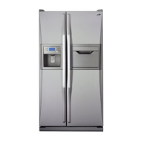
Diagram showing disassembled parts of the CABINET section for FRS(N)-U20IA model.
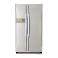
Diagram showing disassembled parts of the CABINET section for FRS(N)-U20DA model.
Diagram showing disassembled parts of the CABINET section for FRS(N)-U20EA model.
Diagram showing disassembled parts of the CABINET section for FRS(N)-U20FA model.
Diagram showing disassembled parts of the CABINET section for FRS(N)-U20GA model.
| Brand | Daewoo |
|---|---|
| Model | FRS(N)-U20IA |
| Category | Refrigerator |
| Language | English |