3
CLUTCH
Description of components CF65/75/85 series
3-10
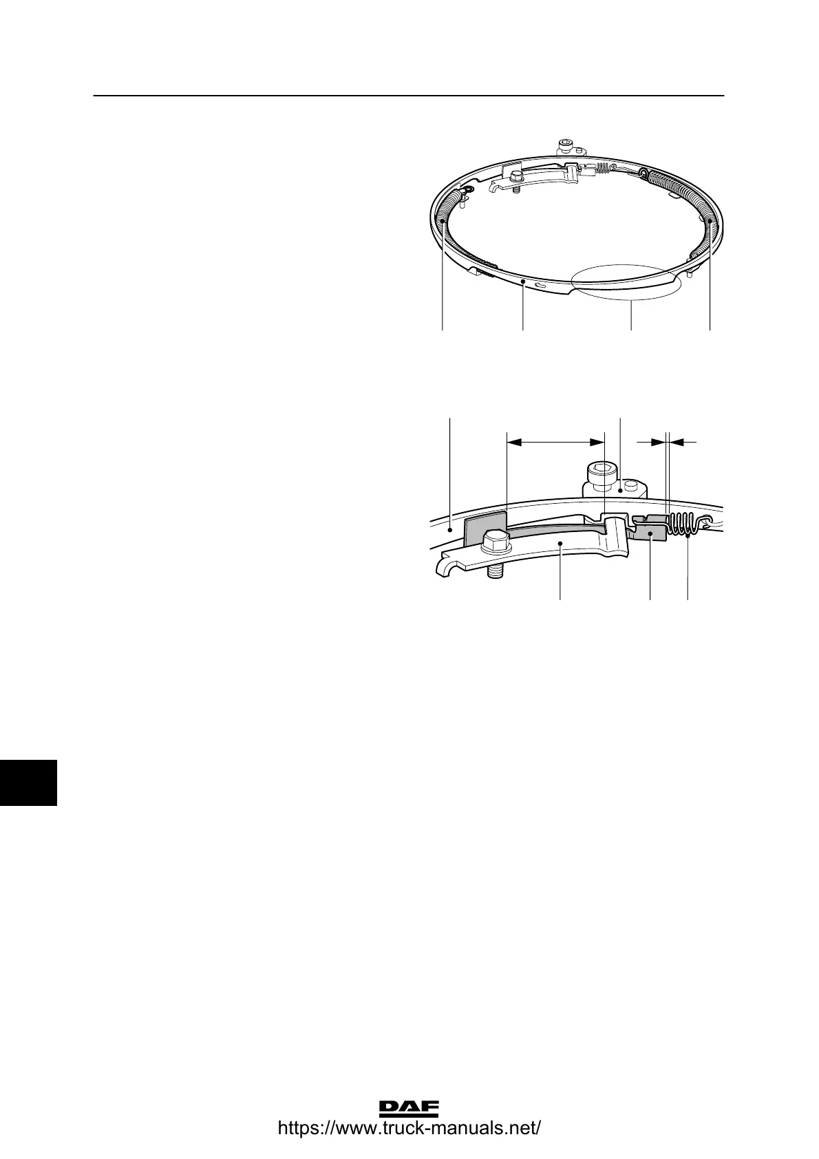
The adjusting ring (6) twists as a result of the
tension applied by the adjusting springs (10).
The adjusting ring twists by the same amount as
the former gap (B) in the recess in the adjusting
ring (6).
The contact surface (E) between the adjusting
ring and the thrust plate is wedge-shaped.
Adjusting the adjusting ring (6) causes it to move
upwards. This causes the space (C) between
the thrust plate (1) and the diaphragm spring (8)
to close. When the clutch is no longer being
used, the diaphragm spring will return to the
same rest position. This procedure
compensates for wear in the clutch plate and
ensures that the diaphragm spring always
returns to the same rest position.
V300486
5 E 1010
Compensation occurs during the first 4 mm of
clutch plate wear.
This is determined by the maximum adjustment
distance (D). Adjustment ceases when the slide
plate (7) rests against the stop of the stop
spring (5).
Once the clutch plate has worn by 4 mm, the
automatically adjusting clutch behaves as a
conventional clutch if there is any further wear.
In other words, the position of the diaphragm
spring will change once there is more than 4 mm
of wear.
This results in a change in the position of the
clutch lever and the clutch servo thrust pin and
in the position of the wear indicator. The
wear indicator will only give a wear indication
during the last millimetre of wear of the clutch
plate lining.
V300485
6
BD
2
9
75
10
ᓻ 200337
https://www.truck-manuals.net/
 Loading...