3
CLUTCH
Description of components CF65/75/85 series
3-12
3.6 CF75/85 CLUTCH WEAR INDICATOR
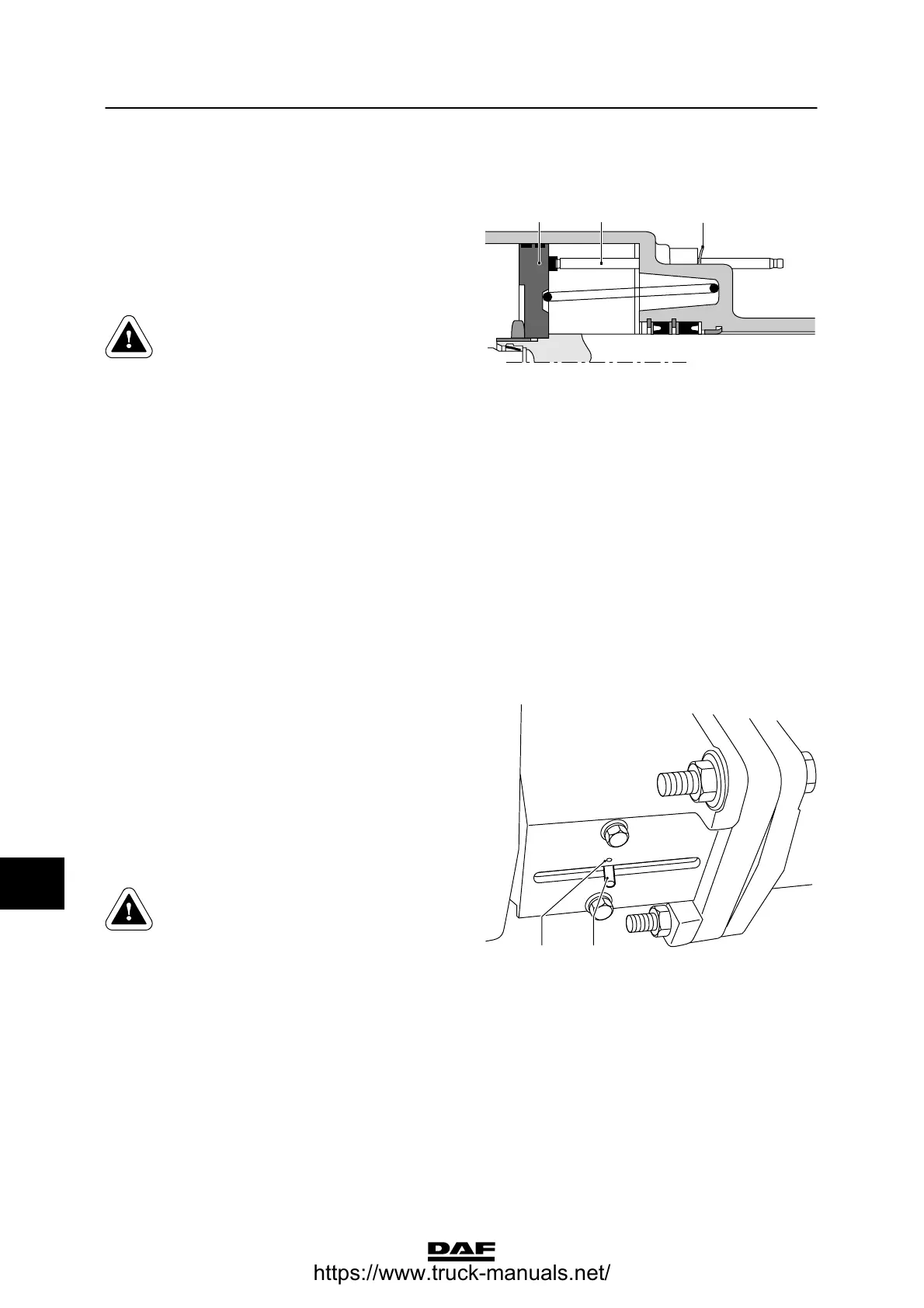
CF75 and CF85 wear indicator
The wear indicator consists of a pin (11) which
protrudes out of the clutch servo housing. The
part of the pin within the clutch servo lies loose
against the air piston (5). A circlip (12) is placed
on the outer part of the pin.
This circlip must be pressed against
the clutch servo during the first
service inspection. It is not allowed
to remove the circlip or to move the
circlip over the pin. This is to
prevent inaccurate indication.
When the clutch plate shows wear of around
80%, the air piston (5) will push the pin (11)
outwards. The reason for this is that the
automatically adjusting clutch assembly cannot
be adjusted any more when the clutch plate
shows wear of 80%. Among other things, the
position of the air piston (5) and consequently
the pin (11) changes. The circlip (12) on the pin
(11) will no longer lie against the housing of the
clutch servo. The movement of the (indicator)
circlip (12) may be approx. 10 mm.
V300355
5 11
12
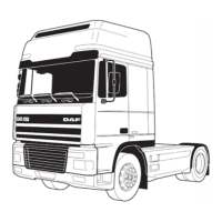
3.7 CF65 CLUTCH WEAR INDICATOR
CF65 wear indicator
There is an indicator (2) mounted on the clutch
servo pressure pin. The end of the indicator can
be seen in the indicator cover groove.
When the clutch plate shows a wear of around
80%, the indicator (2) will assume a different
position in relation to its initial position. The initial
positionisindicatedbyamark(1)onthe
indicator cover. The maximum movement of the
indicator is around 5 mm.
The mark is made on the indicator
cover by means of a centre punch.
The mark must be placed in precise
correspondence to the centre of the
indicator.
This must be done during the first
service inspection.
V3 00 375
12
10
ᓻ 200337
https://www.truck-manuals.net/