EasyManua.ls Logo

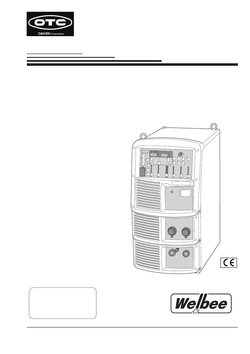
Daihen OTC Welbee P500L - User Manual

Daihen OTC Welbee P500L
158 pages
Print Icon
To Next Page IconTo Next Page
Loading...
E n s u r e t o r e a d t h i s
i n s t r u c t i o n m a n u a l
thoroughly for safe and
proper use of the product.
October, 2013
Manual No. : 1P30137-1
Model: WB-P500L
Welbee Inverter
P500L
OWNER'S MANUAL
Pulse MAG/MIG
Welding power source
DAIHEN Corporation

Table of Contents

Questions and Answers

  • C
    cooperdouglasAug 2, 2025
    Why is the arc unstable on my Daihen Portable Generator?
    • A
      Amy WebbAug 2, 2025
      If the arc from your Daihen Portable Generator is unstable, consider these potential causes: * Incorrect welding mode settings: Verify the wire diameter, wire materials, and shielding gas settings. * Defective wire or wire feeding issues: Inspect the wire and wire feeder for any problems. * Incorrect voltage detection cable connection: Ensure the voltage detection cable is properly connected. * Noise in the voltage detection cable: Adjust the arc characteristics to the plus side.
  • K
    Kevin NielsenAug 6, 2025
    What to do if the wire is not fed on my Daihen Portable Generator?
    • D
      Dustin ToddAug 6, 2025
      If your Daihen Portable Generator isn't feeding wire (and no error code appears), it could be due to: * The pressure roll of the wire feeder came off. You should correctly set the pressure roll of wire feeder. Consult the wire feeder's instruction manual for setting instructions. * Abnormalities in the wire feeder cables. Make sure that there is no abnormality in cables of the wire feeder.
  • B
    Brooke HensleyAug 10, 2025
    Why are there blowholes when using my Daihen Portable Generator?
    • B
      brittanysimmonsAug 10, 2025
      If you notice blowholes when using your Daihen Portable Generator, it might be due to: * A problem with the shielding gas. Check the gas cylinder and gas hose for any issues. * A worn-out welding torch chip. Replace the chip.
  • K
    Kristina LeonAug 15, 2025
    What to do if the power LED switch does not light on Daihen Portable Generator?
    • A
      amy86Aug 15, 2025
      If the power LED switch on your Daihen Portable Generator doesn't light up when you turn on the power switch, it's likely that the primary power source isn't being supplied. Make sure to supply the primary power source between 340 to 460 V.
  • S
    Stephen BatesAug 19, 2025
    How to disable the erroneous operation prevention function on Daihen Portable Generator?
    • S
      Sarah LopezAug 19, 2025
      If the power condition cannot be set or the welding mode does not change on your Daihen Portable Generator, it could be that the erroneous operation prevention function is enabled. Press and hold the ENTER key for at least three seconds to disable this function.
  • A
    Abigail MatthewsAug 23, 2025
    What to do if the power switch has tripped on my Daihen Portable Generator?
    • T
      tgonzalezAug 23, 2025
      If the Daihen Portable Generator's power switch has tripped and a leak has occurred in the welding power source, DO NOT turn on the power switch. Contact your dealer.
  • P
    pthompsonAug 28, 2025
    What does continuous WCR signal output on Daihen Portable Generator mean?
    • C
      Cynthia MillerAug 28, 2025
      If the monitor of the robot shows continuous output of the WCR signal on your Daihen Portable Generator, the WCR relay of the welding power source may be broken. The WCR relay on the printed circuit board PCB1 (P30099P00) needs to be replaced. Contact your dealer.

Summary

Chapter 1 Safety Information

1.1 Warning Symbols

Explains safety warning symbols used for hazard identification.

1.2 Safety Precaution

General safety guidelines for operating the welding power source.

1.2.1 Operating precautions

Safety measures during welding operations.

1.2.2 Precautions for power supply and electric shock

Guidelines to prevent electric shock hazards.

1.2.4 Precautions for flammable materials

Measures to prevent fire and explosion risks.

1.2.5 Precautions for gas cylinder and gas regulator

Safe handling of gas cylinders and regulators.

1.2.8 Precaution for protective equipment

Essential personal protective equipment for welding.

1.3 Principal Safety Standards

Lists key safety standards relevant to welding equipment.

Chapter 2 Product Specification and Configuration

2.1 Specification

Details the technical specifications of the welding power source.

2.1.1 Specifications

Lists key technical data like voltage, current, and dimensions.

2.1.2 Applicable welding method

Outlines supported welding methods, gases, and materials.

2.1.4 Rated duty cycle

Specifies the operational duty cycle limits.

2.2 Product Configuration

Describes the components included with the unit.

2.2.1 Standard composition

Lists standard equipment included in the package.

2.2.3 Accessory (not supplied)

Lists accessories the customer must provide.

2.2.4 Optional accessories

Lists optional add-on items.

2.3 Part Names

Identifies components on the front and rear panels.

2.3.1 Front panel

Details components on the front of the unit.

Chapter 4 Connection

4.1 Precautions for Connection Procedure and Grounding

Essential safety steps before connecting the equipment.

4.2 Connecting the Welding Power Source

Step-by-step guide for connecting all components.

4.2.1 Connection of cable at output side

How to connect output cables.

4.2.2 Connection of wire feeder

Connecting the wire feeder unit.

4.2.3 Connection of welding torch

Connecting the welding torch.

4.3 Grounding and Connection of Input Power Supply

Proper grounding and input power connection.

4.5 Connection of External Equipment

Connecting external devices like robots.

4.5.1 Connection of robot

Specifics for robot integration.

Chapter 5 Welding Operation

5.1 Precaution at Welding Operation

Safety measures before and during welding.

5.1.2 Precaution for protective equipment

Guidelines for personal protective equipment.

5.2 Check before Welding

Crucial checks before initiating welding.

5.3 Power ON and Gas Supply

Procedure for powering up and supplying shielding gas.

5.4 Wire Inching

How to feed the welding wire.

5.5 Check and Setting of Welding Condition

Verifying and adjusting welding parameters.

5.5.2 Preventing erroneous operation on operation panel

Enabling panel lock to prevent accidental changes.

5.6 Performing Welding Operation

Steps for executing the welding process.

5.6.1 Operation of welding start

How to initiate the welding arc.

5.6.2 Operation during welding

Adjusting current and voltage during welding.

Chapter 6 Welding Condition

6.1 List of Welding Conditions

Overview of available welding parameters.

6.1.1 Parameter (Welding parameter)

Detailed list of welding parameters.

6.1.3 Internal function

Settings for internal operational functions.

6.2 Function on Operation Panel

Explanation of the control panel layout and keys.

6.4 Preparing Welding Conditions

Step-by-step process for setting welding parameters.

6.5 Memory Function of Welding Conditions

How to save and recall welding settings.

6.5.1 Memory registration of welding conditions

Procedure to save current settings.

6.5.2 Read out of welding conditions

Procedure to load saved settings.

6.6 Setting Welding Conditions

Detailed guide to setting welding parameters.

6.6.1 Welding mode setting

How to select different welding modes.

6.6.2 Setting welding parameter

Setting parameters for different welding sequences.

6.6.2.2 Welding parameter setting

Step-by-step parameter adjustment.

6.6.3 Crater setting

Options for crater fill and arc spot.

6.6.5 Welding voltage adjustment

How to adjust welding voltage.

6.6.7 Penetration control adjustment

Adjusting weld penetration depth.

Chapter 7 Administrator Functions

7.1 Protection of Welding Conditions

Securing welding settings with a password.

7.1.1 Setting;Changing password

Procedure to set or change the password.

7.1.2 Disabling erroneous operation prevention

How to unlock the operation panel.

7.2 Welding Result Control Function

Functions for monitoring and controlling weld quality.

7.2.1 Setting welding result control function

How to configure weld quality monitoring.

7.2.2 Details of welding control items

Explanation of specific weld control parameters.

7.2.2.1 Number of welding point

Control based on weld count.

7.2.2.2 Wire consumption

Control based on wire usage.

7.2.2.4 Welding monitor

Real-time monitoring of welding parameters.

7.3 Data Backup (Utilization of data)

Backing up and restoring settings.

7.3.4 Backup operation

Steps to back up data to a USB drive.

7.3.5 Importing backup data

Steps to import data from a USB drive.

7.4 Initializing Welding Conditions and Internal Functions

Resetting the unit to factory defaults.

Chapter 8 Maintenance and Inspection

8.1 Precautions for Maintenance and Inspection

Safety guidelines for performing maintenance.

8.2 Daily Inspection

Routine checks to perform daily.

8.3 Periodical Inspection

Periodic inspections and cleaning procedures.

8.4 Periodical Replacement Parts

Identification of parts that require periodic replacement.

Chapter 9 Troubleshooting

9.1 Action in Case of Error

How to interpret and resolve error codes.

9.2 Troubleshooting

General guidance for common problems and their solutions.

Chapter 10 Reference Materials

10.1 Parts List

A comprehensive list of all replaceable parts.

10.2 Reference Drawing

Contains schematic and layout diagrams.

10.2.1 Schematic diagram

The electrical schematic of the unit.

10.3 Materials for Setting Welding Conditions

Information to help set optimal welding parameters.

10.3.2 Samples of welding condition settings

Provides examples of welding settings for various applications.

Daihen OTC Welbee P500L Specifications

General IconGeneral
BrandDaihen
ModelOTC Welbee P500L
CategoryPortable Generator
LanguageEnglish

Related product manuals