Do you have a question about the Daikin AWV018 and is the answer not in the manual?
Checklist for chilled water system installation and preparation.
Checklist for electrical connections and power readiness.
Checklist for general installation and testing items.
Crucial safety precautions and hazard identification for equipment operation.
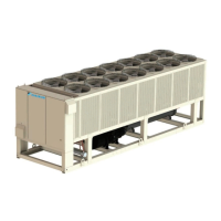
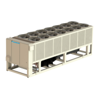
Instructions for correctly positioning and rigging the chiller unit for installation.
Guidelines for maintaining adequate spacing around the unit for optimal airflow.
Specifications and guidelines for installing chilled water piping connections.
Recommendations for preventing evaporator freeze-up in cold environments.
Safety and code compliance for electrical wiring and connections.
Guidelines for designing refrigerant piping for remote evaporator systems.
Overview of the MicroTech III control system and its capabilities.
Features of the controller, including readouts, control functions, and alarm diagnostics.
Explanation of unit-level settings that can be adjusted during operation.
Details on set points that apply individually to each circuit.
Methods to protect the evaporator and piping from freezing temperatures.
Methods for controlling unit capacity via compressor staging and loading.
How unit capacity is limited by internal settings, demand limit, or network commands.
How compressors are controlled via VFDs, solenoids, and motor speed.
Detailed states and control logic for the evaporator electronic expansion valve (EXV).
EXV control states for MOP and Superheat, including target calculations.
How unit capacity is limited when evaporator LWT exceeds a critical threshold.
How alarms are logged, signaled, and displayed within the system.
Details on Ground Fault Protection alarms for the unit and individual circuits.
Alarms related to evaporator flow loss and water freeze protection.
Alarms for inverted water temperatures and LWT/EWT sensor faults.
Alarms for faults in evaporator EWT, OAT, and discharge temperature sensors.
Alarms indicating communication failures with control modules (AC, EXV, DC Fan).
Alarms triggered by emergency stop activation or external alarm inputs.
Alarms triggered by low evaporator pressure conditions.
Alarms for high condenser pressure and low pressure difference or ratio conditions.
Alarms triggered by mechanical low or high pressure switches.
Alarms for high discharge temperature and compressor motor temperature.
Alarms for high oil pressure difference and compressor start failures.
Alarms for low discharge superheat and high motor current conditions.
Alarms related to VFD temperature, communication, and general faults.
Alarms for communication failures with CC, EEXV, and other control modules.
Alarms indicating faults with pressure, oil, and suction temperature sensors.
Alarms for discharge temperature sensor faults and EXV motor errors.
Overview of the controller's display, buttons, and navigation methods.
Pre-startup checks and completion of the checklist before initial startup.
Step-by-step guide for starting the chiller unit and setting initial parameters.
Importance of checking electrical terminal tightness and safety precautions.