3 | Components
Service manual
103
EBLA09~16DA + EDLA09~16DA
Daikin Altherma 3 M
ESIE20-06A – 2021.03
b 4‑way valve
5 Stop the nitrogen supply when the piping has cooled down.
6 Remove the 4‑way valve.
INFORMATION
It is ALSO possible to cut the component pipe(s) using a pipe cutter. Make sure to
remove the remaining component pipe end(s) from the refrigerant pipes by heating
the brazing point(s) of the component pipe(s) using an oxygen acetylene torch.
7 Install plugs or caps on the open pipe ends of the refrigerant piping to avoid
dirt or impurities from entering the piping.
8 To install the 4‑way valve body, see "3.2.2Repair procedures"[4101].
To install the 4-way valve body
1 Remove the plugs or caps from the refrigerant piping and make sure they are
clean.
2 Remove the 4‑way valve coil from the spare part 4‑way valve body.
3 Install the 4‑way valve body in the correct location and correctly oriented.
Insert the pipe ends in the pipe expansions.
4 Supply nitrogen to the refrigerant circuit. The nitrogen pressure MUST NOT
exceed 0.02MPa.
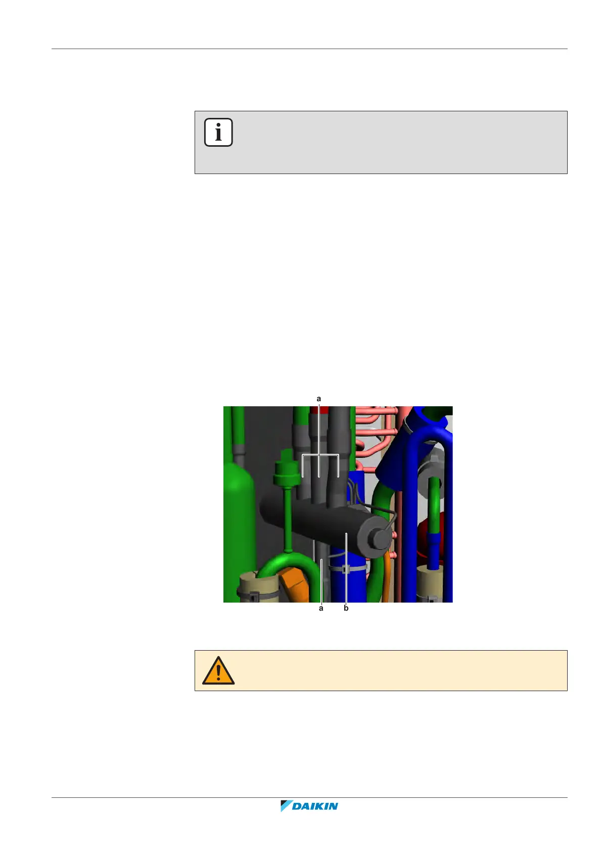
5 Wrap a wet rag around the 4‑way valve body and any other components near
the 4‑way valve and solder the 4‑way valve pipes to the refrigerant pipes.
a 4‑way valve pipe
b 4‑way valve
CAUTION
Overheating the valve will damage or destroy it.
6 After soldering is done, stop the nitrogen supply after the component has
cooled‑down.
7 Install the putty (if available) and the insulation (if available) in their original
location.
8 Install the 4‑way valve coil on the 4‑way valve body, see "3.2.2 Repair
procedures"[4101].