English 10
CAUTION
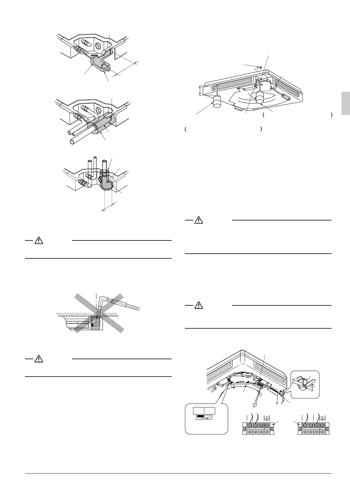
• Do not twist or bend the drain hose (1), so that exces-
sive force is not applied to it, as this could cause leaks.
PRECAUTIONS FOR UPWARD DRAIN RAISING PIPING
• Install the drain raising pipes at a height of less than
500mm.
• Install the drain raising pipes at a right angle to the
indoor unit. (Refer to Fig. 29)
CAUTION
If the upward running drain hose leans at a slant, the float
switch will malfunction and water will leak.
7-2 After piping work is finished, check if drainage
flows smoothly.
• Open the water inlet lid, add approximately 1000cc of
water slowly and check drainage flow. (Refer to Fig. 30)
[Caution]
Drain piping connections
• Do not connect the drain piping directly to sewage pipes that
smell of ammonia. The ammonia in the sewage might enter
the indoor unit through the drain pipes and corrode the heat
exchanger.
WHEN ELECTRIC WIRING WORK IS FINISHED
• Check drainage flow during Cooling operation, explained
under “TEST OPERATION”.
WHEN ELECTRIC WIRING WORK IS NOT FINISHED
CAUTION
• Electrical wiring work should be done by a certified electri-
cian.
• If someone who does not have the proper qualifications per-
forms the work, perform the following after the test run is
complete.
• Remove the control box lid and change the emergency
switch above the PC board assembly of the indoor unit from
“NORM.” to “EMERG.”. Connect the single-phase power
supply and earth wire to the power supply (50Hz 220-240V)
terminal board and confirm drain operation.
Be sure to change the switch before turning on the power.
(Refer to Fig. 31)
CAUTION
• Clamp solidly to clamp C to make sure no excess pressure
is applied to the wiring connections.
• Be aware that the fan will turn during the operation.
• After confirming drainage, turn off the power and be sure to
change the emergency switch back to “NORM.”.
Clamp (2)
Clamp (2)
Clamp (2)
Sealing pad (8)
Sealing pad (8)
Sealing pad (8)
Elbow (9)
Drain hose (1)
Short end
Upward
running
pipe
Elbow (9)
Fig. 28
Long
end
WRONG
Fig. 29
Service cover
≥100
≥100
Plastic watering can
(Tube should be about 100mm long.)
Inspection opening
Service drain outlet
(with rubber plug).
(Use this outlet to drain water
from the drain pan.)
Drain pipe
Method of adding water
Fig. 30
Adding water through air discharge outlet
Adding water from inspection opening
Power supply terminal board
Indoor PC
board
assembly
Single phase power supply
Fig. 31
Clamp C
Tab
123
Power
supply
terminal
board
123
(FUQ model) (Other models)
NORM.
EMERG.
Emergency switch
(Normal, Emergency)
Clamp C
01_EN_3P249378-5G.fm Page 10 Friday, January 20, 2012 2:01 PM
 Loading...