4 English
(length: mm)
(2)
Make sure the range of the unit’s external static pres-
sure is not exceeded.
(See the technical documentation for the range of the
external static pressure setting.)
(3)
Open the installation hole. (Pre-set ceilings)
•
Once the installation hole is opened in the ceiling where
the unit is to be installed, pass refrigerant piping, drain
piping, transmission wiring, and remote controller wiring
(It is not necessary if using a wireless remote controller)
to the unit’s piping and wiring holes.
See “6. REFRIGERANT PIPING WORK”, “7. DRAIN
PIPING WORK”, and “10. WIRING EXAMPLE”.
•
After opening the ceiling hole, make sure ceiling is level if
needed. It might be necessary to reinforce the ceiling
frame to prevent shaking.
Consult an architect or carpenter for details.
(4)
Install the suspension bolts.
(Use W3/8 to M10 suspension bolts.)
Use a hole-in-anchor for existing ceilings, and a sunken
insert, sunken anchor or other part to be procured in the
field to reinforce the ceiling to bearing the weight of the unit
for new ceiling. (Refer to Fig. 3)
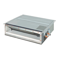
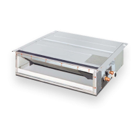
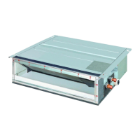
(5)
For bottom intake, replace the chamber lid in the pro-
cedure listed in Fig. 4.
(1) Remove the chamber lid. (7 locations)
(2) Reattached the removed chamber lid in the orientation
shown in Fig. 4. (7 locations)
(3) Attach the air filter (accessory) in the manner shown in
the diagram.
The four holes which cannot be covered by the air filter
should be covered with commercially available tape.
Model A B
20 · 25 · 32 · 40 · 50 type 900 940
63 type 1100 1140
B
A
620
500
450×450
(Inspection
opening size)
Ceiling
620
A
Air outlet
Suspension
bolt pitch
(length : mm)
Air inlet
Control box
(Suspension bolt pitch )
Allow view
Inspection door
(Ceiling opening)
Fig. 2
〈
SERVICE SPACE
〉
Drain pump
Note: All the above parts are field supplied.
Suspension bolt
Long nut or turn-buckle
Anchor bolt
Indoor unit
Ceiling slab
Fig. 3
Air inlet
(1)
(2)
Fig. 4
Air outlet
Air inlet
Air outlet
Chamber lid
Chamber lid
01_EN_3PN06588-2C.fm Page 4 Tuesday, November 29, 2005 2:25 PM
 Loading...