Donotmixsubstanceotherthanthespeciedrefriger-
ant such as air into the refrigeration circuit.
If the refrigerant leaks during the work, ventilate the
room.
• The refrigerant is pre-charged in the outdoor unit.
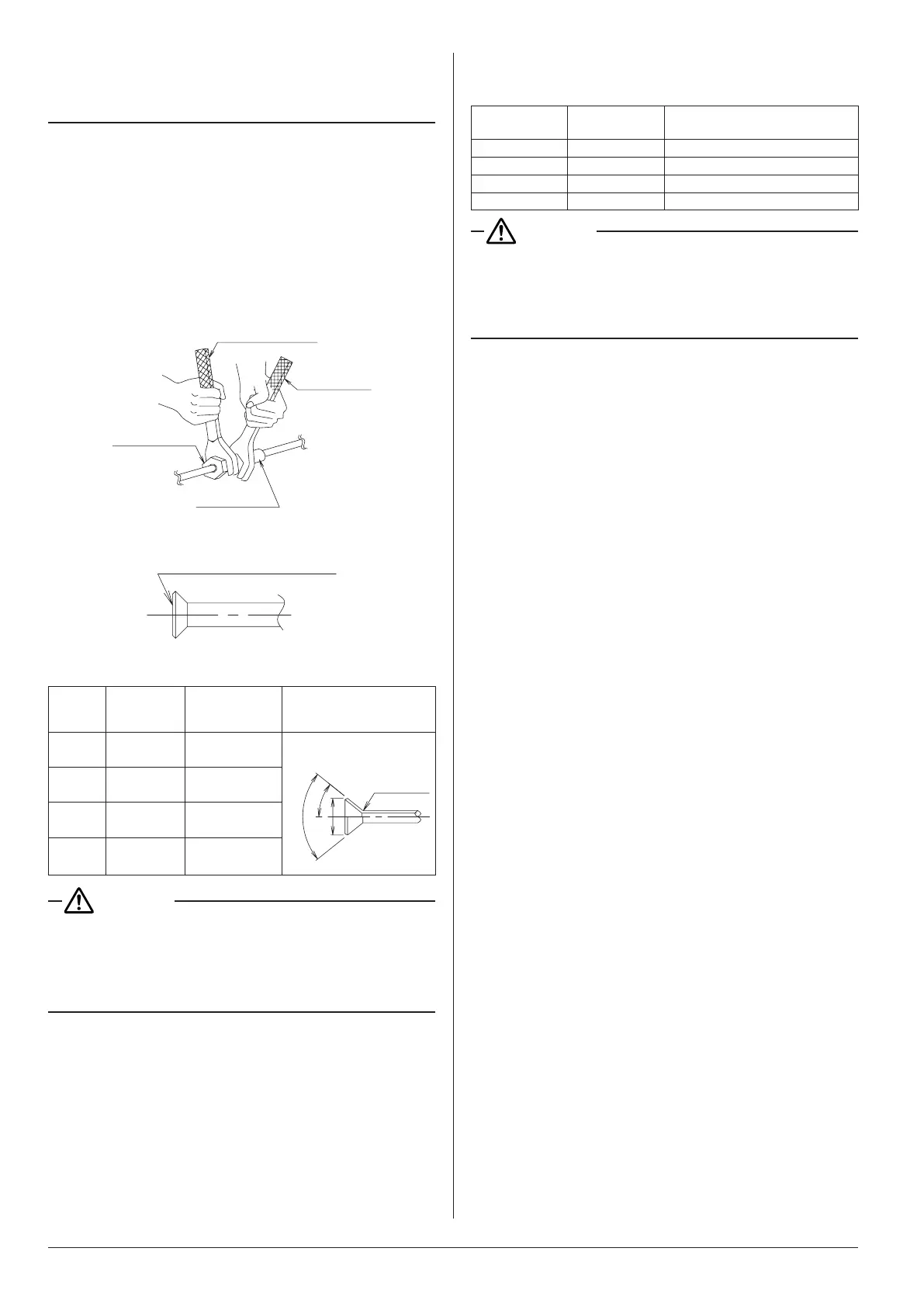
• When connecting the pipings to the air conditioner, make
sure to use a spanner and a torque wrench as shown in
Fig. 10.
• Forthedimensionofaredpartandthetighteningtorque,
refer to the Table 2.
• Whenmakingaareconnection,coatthearedinner
surface only with ether oil or ester oil.
(Refer to Fig. 11)
Then,turnthearenut3to4timeswithyourhandand
screw in the nut.
Spanner
Flare nut
Union joint
Fig. 10
Coat the flared inner surface
only with ether oil or ester oil
Fig. 11
Table 2
Piping
size
(mm)
Tightening
torque
(N·m)
Dimension for
processing flare
A (mm)
Flare shape
f
6.4
15.7 ± 1.5 8.9 ± 0.2
R0.4-0.8
A
f 9.5
36.3 ± 3.6 13.0 ± 0.2
f
12.7
54.9 ± 5.4 16.4 ± 0.2
f
15.9
68.6 ± 6.8 19.5 ± 0.2
CAUTION
Donothaveoiladheretothescrewxingpartofresin
parts.
If oil adheres, it may weaken the strength of screwed part.
Donottightenarenutstootight.
If a flare nut cracks, the refrigerant may leak.
• If there is no torque wrench, use Table 3 as a rule of
thumb.
Whentighteningaarenutwithaspannerharderand
harder, there is a point where the tightening torque sud-
denly increases.
From that position, tighten the nut additionally the angle
shown in Table 3.
Aftertheworkisnished,checksecurelythatthereisno
gas leak.
If the nut is not tightened as instructed, it may cause slow
refrigerant leak and result in malfunction (such as does
not cool or heat).
Table 3
Piping size
(mm)
Tightening
angle
Recommended arm length of
tool used
f 6.4 60° - 90° approx. 150 mm
f 9.5 60° - 90° approx. 200 mm
f 12.7 30° - 60° approx. 250 mm
f 15.9 30° - 60° approx. 300 mm
CAUTION
Insulationofeldpipingmustbecarriedoutuptothe
connection inside the casing.
If the piping is exposed to the atmosphere, it may cause
sweating, burn due to touching the piping, electric shocks or
a fire due to the wiring touching the piping.
• After leak test, referring to Fig. 12, insulate both the gas
and liquid piping connection with the attached joint in-
sulating material (8) and (9) to prevent the pipings from
getting exposed.
Then, tighten the both ends of insulating material with the
clamp (4).
• Wrap the sealing material (Medium-1, 2) (11) (12) around
thejointinsulatingmaterial(8)and(9)(arenutsection),
both the gas and liquid piping.
• Make sure to bring the seam of joint insulating material (8)
and (9) to the top.
7 3P335596-2D English
 Loading...