Part 5. Installation Manual
128 Design Guide DCM014A51
D. [RESERVE] No Use.
E. [RS-485] The terminals for connecting serial equipment.
F. [plus ADP IF] The terminals for connecting one or more iTM plus adaptors when the iTM is
used to control additional air conditioning devices.
G. [Di (1-4), COM] The terminals for stopping air conditioners when wired to emergency
devices, connecting a power meter to calculate the electricity usage of individual air
conditioners, or other operations.
H. [LAN] The port for connecting the iTM to an Ethernet network.
1.3 Front Panel
• Four LEDs are located below the monitor display on the front panel, and indicate the operating
status of the iTM. Sliding the front slide cover down and removing the cover reveals terminals
used during installation or maintenance work.
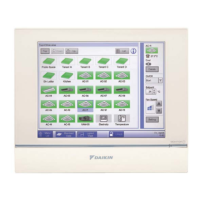
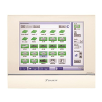
Front face of iTM:
Figure 22. Front Face of intelligent Touch Manager™
A. [SERVICE LAN] The port for temporarily connecting the iTM to a LAN from its front panel
(instead of the rear panel), during installation or maintenance operations.
B. [LAN SW] Switch for setting the LAN port on the back and the SERVICE LAN port on the
front. The cover cannot close when the switch set to “FRONT”. To close the cover, select
“BACK”.
C. [BACKUP] The switch for turning On/Off the backup power supply for retaining the current
settings.
D. [DIII MASTER] The switch for setting “MASTER” or “SLAVE” when there are multiple DIII-Net
centralized controllers such as iTM.
E. [CPU ALIVE] LED (Green): The LED that indicates the CPU is operating normally. The CPU is
operating normally when this LED is blinking, and malfunctioning when it is On or Off. (It
takes about 10 seconds for detection of the abnormality.)
Solid On: Software error
 Loading...