3 | Components
Service manual
103
RXM20~71R + ARXM25~71R + FTXM20~71R + ATXM25~50R +
FVXM25~50A
Split New Perfera R32
ESIE20-11 – 2021.01
Prerequisite: Remove the required plate work, see "3.14Plate work"[4151].
1 Turn ON the power of the unit.
2 Measure the voltage between the pins 1‑4 of the connector S300A on the
innndoor unit main PCB.
Result: The measured voltage MUST be 324VDC.
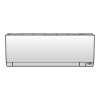
A Wall mounted indoor unit
a Connector S300A
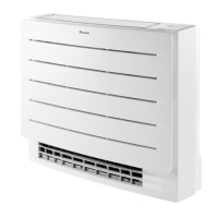
A Floor standing indoor unit
a Connector S300A
Is the measured voltage on the indoor
unit main PCB correct?
Action
Yes Return to "Checking
procedures"[4102] of the indoor unit
main PCB and continue with the next
procedure.
No Continue with the next step.
 Loading...