3 | Components
Service manual
198
RXM20~71R + ARXM25~71R + FTXM20~71R + ATXM25~50R +
FVXM25~50A
Split New Perfera R32
ESIE20-11 – 2021.01
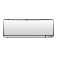
A Wall mounted indoor unit
a Wifi control PCB assembly
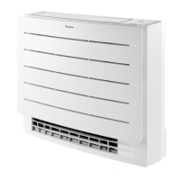
A Floor standing indoor unit
a Wifi control PCB assembly
Is the measured power supply voltage
correct?
Action
Yes Skip the next step..
No Continue with the next step.
4 Measure the output voltage between between the pins 4‑5 on the connector
S801 on the indoor unit main PCB.
Result: The measured voltage MUST be 10~16VDC.
Is the output voltage on the indoor unit
main PCB correct?
Action
Yes Replace the wifi control PCB wiring
harness, see "Repair
procedures"[4199].
No Perform a check of the indoor unit main
PCB, see "Checking procedures"[4102].
5 As there are no further check procedures for this component, perform a check
of the indoor unit main PCB to check if the wifi control PCB needs to be
replaced. See "Checking procedures"[4102].
 Loading...