EasyManua.ls Logo

Daikin RK35JV1NB User Manual

Daikin RK35JV1NB
142 pages
To Next Page IconTo Next Page
Page #1 background imageLoading...
Page #1 background image
SIE-86
Table of Contents i
Inverter Pair
FTK(X)-J / RK(X)-J Series
Cooling Only
Indoor Unit
FTK25JV1NB
FTK35JV1NB
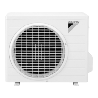
Outdoor Unit
RK25JV1NB
RK35JV1NB
Heat Pump
Indoor Unit
FTX25JV1NB
FTX35JV1NB
Outdoor Unit
RX25JV1NB
RX35JV1NB
Si-86.book Page i Friday, June 23, 2000 10:26 AM

Table of Contents

Questions and Answers:

Daikin RK35JV1NB Specifications

General IconGeneral
Cooling Capacity3.5 kW
Heating Capacity4.0 kW
Energy Efficiency Rating (EER)3.21
Coefficient of Performance (COP)3.61
RefrigerantR32
Weight (Outdoor Unit)30 kg
Noise Level (Outdoor)48 dB(A)
TypeInverter
Power Supply220-240V, 50Hz

Summary

Introduction

Safety Cautions

Read safety cautions before conducting repair work. Cautions are classified into Warning and Caution.

Part 1 List of Function

Part 2 Printed Circuit Board Connector Wiring Diagram

Part 3 Main Function

Defrost Control

Explains the defrost control principle by reversing the cycle from heating to cooling, detailing start and stop conditions.

Input Current Control (H/J Type)

Details frequency control to limit input current within rated values based on detected input current.

Freeze Protection Function in Cooling

Explains how capacity is reduced to prevent freezing of the heat exchanger and dew formation.

Peak-Cut Control Function (H/J Type)

Details peak-cut control to prevent excessive head pressure increase during heating operations.

Compressor Protection Function (H/J Type)

Details control of compressor frequency limit to avoid oil level descent and dilution during operation.

Part 4 System Configuration

Instruction

Troubleshooting: Common Cases

Lists common operational issues like no start, poor cooling/heating, and sudden stops, providing explanations and initial checks.

Troubleshooting: System Checks

Guides on checking power, filters, air flow, settings, and unit status for troubleshooting operational problems.

Part 5 Service Diagnosis

Troubleshooting with Operation Lamp

Explains how the operation lamp indicates errors and guides on diagnostic procedures for unit malfunctions.

Troubleshooting with LED Indication

Details the meaning of green and red LEDs on the outdoor unit PCB for diagnosing equipment conditions.

Problem Symptoms and Measures

Lists common problems and provides measures to check, including power supply, unit type compatibility, and thermistor errors.

Service Check Function: ARC423 Series

Explains how to use the ARC423 series remote controller for service check functions and error code display.

Remote Controller Error Codes

Lists error codes displayed on the remote controller and their corresponding problem descriptions for fault diagnosis.

Troubleshooting: Indoor Units

Provides troubleshooting steps for indoor unit issues, correlating remote controller indications with fault descriptions.

Troubleshooting: Outdoor Units

Details troubleshooting for outdoor units by correlating LED indications and remote controller displays with fault descriptions.

Troubleshooting: Faulty PCB (A1)

Diagnoses faulty PCB (A1) by checking zero-cross detection and connector connections, guiding replacement steps.

Troubleshooting: Operation Shutdown (A5)

Addresses operation shutdown due to high-pressure control or freeze-up protection, guiding checks for air filters and thermistors.

Troubleshooting: Fan Motor Halt (A6)

Guides troubleshooting for fan motor halt due to winding, wire, capacitor, or PCB issues, with detailed checks.

Troubleshooting: Thermistor Abnormality (C4, C9, CA)

Covers operation halt due to thermistor errors, guiding checks for connector connections, thermistor resistance, and PCB issues.

Troubleshooting: Faulty Indoor Unit PCB

Addresses faulty indoor unit PCB issues, guiding checks for power, grounding, and potential external factors causing malfunction.

Troubleshooting: Faulty Indoor Unit PCB (Signal Transmission)

Focuses on faulty indoor unit PCB related to indoor-outdoor signal transmission issues, guiding replacement.

Troubleshooting: Power Supply/PCB Abnormalities (U4)

Covers power supply abnormalities and faulty indoor PCBs (U4), guiding checks for AC voltage, varistors, and fuses.

Troubleshooting: Signal Transmission Error (U4)

Addresses signal transmission errors between units (U4), guiding checks for wiring errors, LED status, and power supply waveform.

Troubleshooting: CT Error (H8)

Covers operation halt due to CT errors (H8), guiding checks for power transistor, wiring, rectifier, and PCB issues.

Troubleshooting: Thermistor Error/Disconnection (J3, J6, H9)

Guides troubleshooting for thermistor errors (J3, J6, H9), covering connector checks, thermistor resistance, and PCB replacement.

Troubleshooting: Compressor Startup Error (E6)

Addresses operation halt due to compressor startup errors (E6), guiding checks for stop valves, power transistor, and compressor.

Troubleshooting: Output Overcurrent (L5)

Covers output overcurrent issues (L5), guiding checks for power transistor, wiring, voltage, PCB, and compressor.

Troubleshooting: Faulty Outdoor Unit PCB

Guides troubleshooting for faulty outdoor unit PCB, checking power, grounding, and potential external factors.

Troubleshooting: Faulty Outdoor PCB/Signal Circuit

Addresses faulty outdoor PCB and signal transmission issues, guiding checks for grounding, power supply waveform, and PCB replacement.

Troubleshooting: Input Over Current (E8)

Covers operation halt due to input over current (E8), guiding checks for wiring errors, power transistor, and PCB.

Check Procedures

Provides a list of check procedures for diagnosing faults, including power transistor, wiring, and installation condition checks.

How to Check: Power Transistor

Details the procedure for checking the power transistor, including capacitor voltage and resistance measurements.

Power Transistor Check Details

Provides specific methods and measurements for checking power transistor functionality and capacitor voltage.

Part 6 Removal Procedure

Related product manuals