EasyManua.ls Logo

Daikin RZQG100L8Y1B Service Manual

Daikin RZQG100L8Y1B
215 pages
To Next Page IconTo Next Page
Page #1 background imageLoading...
Page #1 background image
Service Manual
GQI-Eco Series
Heat Pump R-410A 50Hz
Smart RZQG71~140L9V1
RZQG71~125L9Y1 / RZQG140LY1
Classic RZQSG71L3V1 / RZQSG100~140L9V1
RZQSG100~125L8Y1 / RZQSG140LY1
ESIE15-13B

Table of Contents

Other manuals for Daikin RZQG100L8Y1B

Questions and Answers:

Daikin RZQG100L8Y1B Specifications

General IconGeneral
BrandDaikin
ModelRZQG100L8Y1B
CategoryAir Conditioner
LanguageEnglish

Summary

Introduction

Safety Cautions

Essential safety guidelines for operation and maintenance of Daikin products.

Cautions Regarding Safety of Workers

Safety measures for personnel performing repair work to prevent electric shock and injury.

Cautions Regarding Safety of Users

Safety precautions for end-users to prevent electrical hazards and accidents.

Part 1 - General Information

Model Names of Indoor / Outdoor Units

Lists available indoor and outdoor unit model combinations and their compatibility.

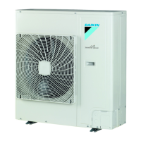
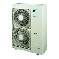
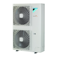
Outlook Outdoor Units

Visual representation of different outdoor unit models for the series.

Operating range

Defines the operational temperature and humidity limits for cooling/heating.

Smart

Defines operational temperature and humidity limits for 'Smart' series models.

Classic

Defines operational temperature and humidity limits for 'Classic' series models.

Part 2 - Remote Controller

Wired Remote Controller

Details on applicable models, names, and functions of wired controllers.

Names and Functions

Explains buttons, icons, and display elements of wired remote controllers.

Wireless Remote Controller

Information on applicable models and functions for wireless controllers.

Names and Functions

Details the functions and operations of wireless remote controllers.

Service Mode

Procedures for accessing and using service modes for diagnostics.

BRC1D528

Procedure to display service data and perform diagnostics on BRC1D528.

Inspection Mode

Steps to enter and utilize the inspection mode for system checks.

BRC1D528

Steps to enter and utilize the inspection mode for system checks.

Part 3 - Function and Control

Function of Main Components and Thermistors

Explains the role of key system components and thermistors.

Operation Flow Chart

Visual representation of the system's operation logic for cooling and heating.

Cooling / Dry Operation

Flowchart detailing the system's operational logic for cooling and dry modes.

Function Details

In-depth explanation of various operational functions and controls.

Indoor Unit

Details indoor unit functions like temperature settings and thermostat control.

Outdoor Unit

Explains outdoor unit functions such as abnormal stops and preheating.

Night-time Quiet Operation

Configuration and activation methods for reducing outdoor unit noise.

Part 4 - Field Setting

Test Operation

Procedures and precautions for performing initial system tests.

Pre-run Checks

Essential checks to perform before initiating a test run of the system.

Field Setting from Remote Controller

Guide to configuring settings using the wired and wireless remotes.

Wired Remote Controller

Instructions for field setting using the wired remote controller.

Remote controller settings

Details various settings configurable via the BRC1E remote controller.

Wireless Remote Controller

Procedure for changing field settings using the wireless remote.

Settings Contents and Code No. for Indoor Units

Table of configurable settings for indoor units with corresponding codes.

Overview of the Field Setting on the Outdoor Units

Summary of field settings applicable to the outdoor unit configurations.

Quiet (Low Noise) Operation

Instructions for setting and activating low noise operation modes via remote.

Setting for Low Humidity Application

Configuration for low humidity operation to enhance cooling capacity.

Field Setting from Outdoor Unit PCB

Instructions for setting parameters using DIP switches on the outdoor PCB.

Location of DIP Switch and BS Button

Identifies DIP switches and BS buttons on the outdoor unit PCB for settings.

Setting Mode 2

Details various operational settings configurable via Setting Mode 2.

Part 5 - Service Diagnosis

Maintenance Inspection

Guidelines for performing routine maintenance checks on the air conditioning unit.

Overview

Guidelines for performing routine maintenance checks on the air conditioning unit.

Symptom-based Troubleshooting

A guide to diagnosing and resolving issues based on observed symptoms.

Equipment does not Operate

Troubleshooting steps for when the equipment fails to start operation.

Indoor Unit Fan Operates, but Compressor does not Operate

Diagnosing why the indoor fan runs but the compressor remains inactive.

Cooling / Heating Operation Starts but Stops Immediately

Steps to resolve issues where the unit starts and stops operation abruptly.

Troubleshooting by LED Indications

Using LED indicators on indoor and outdoor units for fault diagnosis and troubleshooting.

Troubleshooting by Remote Controller

Methods for diagnosing errors using the remote controller display and codes.

Error Codes and Description

Comprehensive list of remote controller error codes and their meanings.

High Pressure Abnormality (Detected by the High Pressure Switch)

Diagnosing high pressure issues detected by the high pressure switch.

Refrigerant Shortage (Error)

Troubleshooting steps for refrigerant shortage errors detected by the system.

Part 6 - Appendix

Piping Diagrams

Visual diagrams illustrating the refrigerant piping layout.

RZQG-L9V1

Visual diagrams illustrating the refrigerant piping layout for RZQG-L9V1 model.

Wiring Diagrams

Electrical wiring diagrams for the outdoor unit.

Outdoor Unit

Electrical wiring diagrams specific to the outdoor unit.

Thermodynamic characteristic of R-410A

Technical data detailing the thermodynamic properties of R-410A refrigerant.

Related product manuals