S
Sharon GomezSep 13, 2025
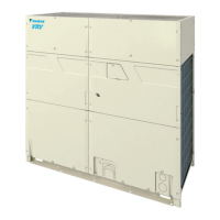
Why is white mist coming out of my Daikin VRV EMERION REYQ192AAYDA Heating System?
- KKathleen Martin DVMSep 13, 2025
If a white mist is coming from your Daikin Heating System, it could be due to high ambient humidity during cooling operation, especially if the indoor unit is installed in a place with much oil or dust. Clean the inside of the indoor unit.