TesƟ ng
WARNING! Read BEFORE Tes ng
• Do not short across terminals on the gas valve or at the hea ng or cooling
system control board to test the thermostat installa on. This could damage
the thermostat and void the warranty.
• Do not select COOL mode if the outside temperature is below 50° F (10° C).
This could damage the controlled cooling system and cause personal injury.
• Ensure the power supply is correct and the display is reading current room
temperature.
Test for ConvenƟ onal System
1. Hold ‘LEFT’ bu on, then momentarily press Reset pinhole.
The screen will go blank. When you see INSTALLATION MODE release ‘LEFT’ bu on.
All outputs are turned off .
2. “HVAC: ELEC Heat/Cool” indicates SW1 is set for Electric Conven onal System.
“HVAC: GAS Heat/Cool” indicates SW1 is set for Gas Conven onal System.
If the display is incorrect, please review SW1 switch posi ons again.
3. “FAN” is highlighted. Press + bu on to toggle the FAN output (ON/OFF). A er
tes ng the FAN output, it is best to keep the FAN output ON to test other outputs.
4. Press
(DOWN) bu on to highlight COOL: “Stage1”. Press + bu on to toggle the
COOL stage 1 output (ON/OFF).
5. Presss
(DOWN) bu on to highlight “Stage 2”. Press + bu on to toggle the COOL
stage 2 output (ON/OFF).
6. Press
(DOWN) bu on to go to the HEAT test. All cool outputs are turned off , the
fan output will be turned off for a GAS System, the fan output will keep current
status for an Electric System.
7. HEAT: “Stage1” is highlighted, press + bu on to toggle the HEAT stage 1 output
(ON/OFF).
8. Press
(DOWN) bu on to highlight “Stage2”. Press + bu on to toggle the HEAT
stage 2 output (ON/OFF).
9. Press
(DOWN) bu on to highlight “Stage3”. Press + bu on to toggle the HEAT
stage 3 output (ON/OFF).
10. Press Reset pinhole to quit INSTALLATION MODE.
Test for 1H1C or 2H1C Heat Pump System
1. Hold ‘LEFT’ bu on, then momentarily press Reset pinhole. The screen will go blank.
When you see INSTALLATION MODE release ‘LEFT’ bu on.
All outputs are turned off .
2. “HVAC: Heat Pump <O>” indicates SW1 is set for cool changeover valve O.
“HVAC: Heat Pump <B>” indicates SW1 is set for heat changeover valve B.
If the display is incorrect, please review SW1 switch posi ons again.
3. The se ng for “STAGE” is highlighted.
Press + bu on to select “1H1C or 2H/1C”.
4. Press
(DOWN) bu on to highlight the se ng for “FAN”.
Press + bu on to toggle the FAN output (ON/OFF).
A er tes ng the FAN output, it is best to keep the FAN output ON while tes ng
other outputs.
5. Press
(DOWN) bu on to highlight the se ng for “COOL: Stage1”.
Press + bu on to toggle the COOL stage 1 output (ON/OFF).
6. Press
(DOWN) bu on to go to the HEAT test. The cool output will be turned off ,
the fan output will keep it’s current status. HEAT: “Stage1” is highlighted.
Press + bu on to toggle the HEAT stage 1 output (ON/OFF).
7. Press
(DOWN) bu on to highlight “AUX”.
Press + bu on to toggle the Auxiliary Hea ng output (ON/OFF).
8. Press
(DOWN) bu on to highlight the “EMER” selec on.
Press + bu on to toggle the EMERGENCY output (ON/OFF).
9. Press Reset pinhole to quit the INSTALLATION MODE.
Test for 2H2C or 3H2C Heat Pump System
1. Hold ‘LEFT’ bu on, then momentarily press Reset pinhole. The screen will go blank.
When you see INSTALLATION MODE release ‘LEFT’ bu on.
All outputs are turned off .
2. “HVAC: Heat Pump <O>” indicates SW1 is set for cool changeover valve O.
“HVAC: Heat Pump <B>” indicates SW1 is set for heat changeover valve B.
If the display is incorrect, please review SW1 switch posi ons again.
3. The se ng for “Stage” is highlighted.
Press
(DOWN) bu on to select “2H2C or 3H2C”.
4. Press
(DOWN) bu on to highlight the se ng for “FAN”.
Press + bu on to toggle the FAN output (ON/OFF).
A er tes ng the FAN output, it is best to keep the FAN output ON while tes ng
other outputs.
5. Press
(DOWN) bu on to highlight the se ng for COOL: “Stage1”.
Press + bu on to toggle the COOL stage 1 output (ON/OFF).
6. Press
(DOWN) bu on to highlight “Stage2”.
Press + bu on to toggle the COOL stage 2 output (ON/OFF).
7. Press
(DOWN) bu on to go to the HEAT test. All cool outputs will be turned off ,
the fan output will keep current status. HEAT: “Stage1” is highlighted.
Press + bu on to toggle the HEAT stage 1 output (ON/OFF).
8. Press
(DOWN) bu on to highlight “Stage2”.
Press + bu on to toggle the HEAT stage 2 output (ON/OFF).
9. Press
(DOWN) bu on to highlight “AUX”.
Press + bu on to toggle the Auxiliary Hea ng output (ON/OFF).
10. Press
(DOWN) bu on to highlight the “EMER” se ng.
Press + bu on to toggle the EMERGENCY output (ON/OFF).
11. Press Reset pinhole to quit the INSTALLATION MODE.
Joining the ZigBee Wireless Network
A er successfully comple ng the Installa on Test the WTS10 is ready to communicate
with the Daintree Wireless Area Controller (WAC) and be commissioned and confi gured
using the ControlScope Manager (CSM) web-based applica on. Note that the WAC must
be commissioned before the thermostat can join the ZigBee wireless network.
1. Using the CSM web interface, go to the Confi guraƟ on menu, then select Add New
Devices.
2. At the Stage 1 screen select the WAC to which you want to add the thermostat.
Click Next. The CSM will begin discovering new and unconfi gured ZigBee devices.
3. Go to the thermostat and press the MIDDLE bu on to ac vate the display.
• If JOIN appears, press the bu on below it (RIGHT bu on).
• If JOIN does not appear press the LEFT bu on to open the thermostat Menu.
a. Press the
(DOWN) bu on 5 mes to advance the Menu display to the
second page, showing
NETWORK.
b. Press the MIDDLE bu on to SELECT the Network func on.
3. Press the MIDDLE bu on to select SCAN. The thermostat will scan all channels.
4. When the thermostat fi nds a suitable channel, a 16-character ID and JOIN appears
in the display. Press the thermostat’s MIDDLE bu on to have it JOIN the network.
5. “Joined successful” appears in the display. Look at the New and Unconfi gured
devices list in CSM to confi rm that the Thermostat has been discovered.
6. Click Next on the CSM screen to proceed with commissioning.
For informaƟ on about confi guring the thermostat using CSM, see the on-line help.
Click the
Help link near the upper-right corner of the CSM screen.
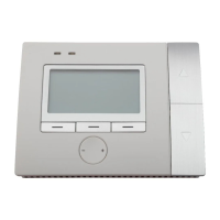
LED OperaƟ on
The WTS10 has two LEDs above the display. Upon power-up the LEDs cycle on and off
briefl y as the thermostat goes through its start-up rou ne. A er the start-up rou ne is
complete, the LEDs operate as described in the table below.
LeŌ (orange) LED DescripƟ on
Not lit Normal opera on.
Orange, fl ashing
Bootloader reprogramming MCU a er OTA
fi rmware update performed successfully.
Right (mulƟ color) LED DescripƟ on
Not lit Normal opera on while joined to ZigBee network.
Red, solid Thermostat has not joined a ZigBee network.
Green, fl ashing Thermostat is scanning for a network to join.
Green, solid for 3 seconds Thermostat has joined a ZigBee network.
Amber, solid
HVAC system warning: 24VAC is detected at
thermostat’s L terminal.
Amber, fl ashing
Thermostat is responding to an “Iden fy”
command from CSM.
UP
DOWN
MIDDLE
LEFT
RIGHT
Reset
Pinhole
Orange
off = normal operation
Multicolor
(Red, Amber, or Green)
Red: Not joined
Green flashing: Network
join scan in progress
Green for 3 seconds: Join
successful
mber: HVAC Warning
mber flashing: CSM
“identify” response
NIGHT
FAN AUTO
HEAT
MENU
MON May 16
11:23a
67
F
°
63
Copyright © 2013, Daintree Networks, Inc. All rights reserved.
ZigBee® is a registered trademark of the ZigBee Alliance.
Daintree Networks, Inc.
(p) +1 (650) 965 3454 (e) info@daintree.net (w) www.daintree.net
technical support (p) (650) 316 8412 (e) support@daintree.net
 Loading...