DS1821
6 of 18
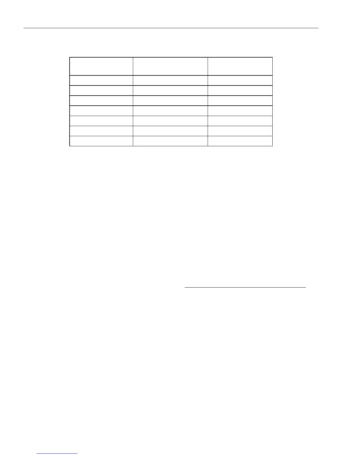
TEMPERATURE/DATA RELATIONSHIP Table 2
TEMPERATURE
DIGITAL OUTPUT
(Binary)
DIGITAL OUTPUT
(Hex)
+125°C* 0111 1101 7Dh
+85°C 0101 0101 55h
+25°C 0001 1001 19h
0°C 0000 0000 00h
-1°C 1111 1111 FFh
-25°C 1110 0111 E7h
-55°C 1100 1001 C9h
HIGH-RESOLUTION TEMPERATURE READINGS
The user can calculate temperature values with higher than 8-bit resolution using the data remaining in
the counter and slope accumulator when the temperature conversion is complete. To do this the user must
first read the temperature from the 8-bit temperature register. This value is called TEMP_READ in the
high-resolution equation (see Eq. 1). The 9-bit counter value must then be obtained by issuing the Read
Counter [A0h] command. This value is the count remaining in the counter at the end of the gate period
and is called COUNT_REMAIN in Eq. 1. Next the Load Counter [41h] command must be issued, which
loads the 9-bit slope accumulator value into the counter register. The slope accumulator value (called
COUNT_PER_C in Eq. 1) can then be read from the counter by again issuing the Read Counter [A0h]
command. The slope accumulator value is called “COUNT_PER_C” because it represents the number of
counts needed for an accurate measurement at a given temperature (i.e., the counts per degree C). The
high-resolution temperature can then be calculated using Eq. 1:
Eq. 1) TEMPERATURE = TEMP_READ
−
0.5 +
CPERCOUNT
REMAINCOUNTCPERCOUNT
__
)___(
High-resolution temperature readings cannot be used while in continuous conversion mode. Also, the
Read Counter [A0h] and Load Counter [41h] commands must not be used while in continuous conversion
mode.