1 - 5
SEQUENCE OF
OPERATION
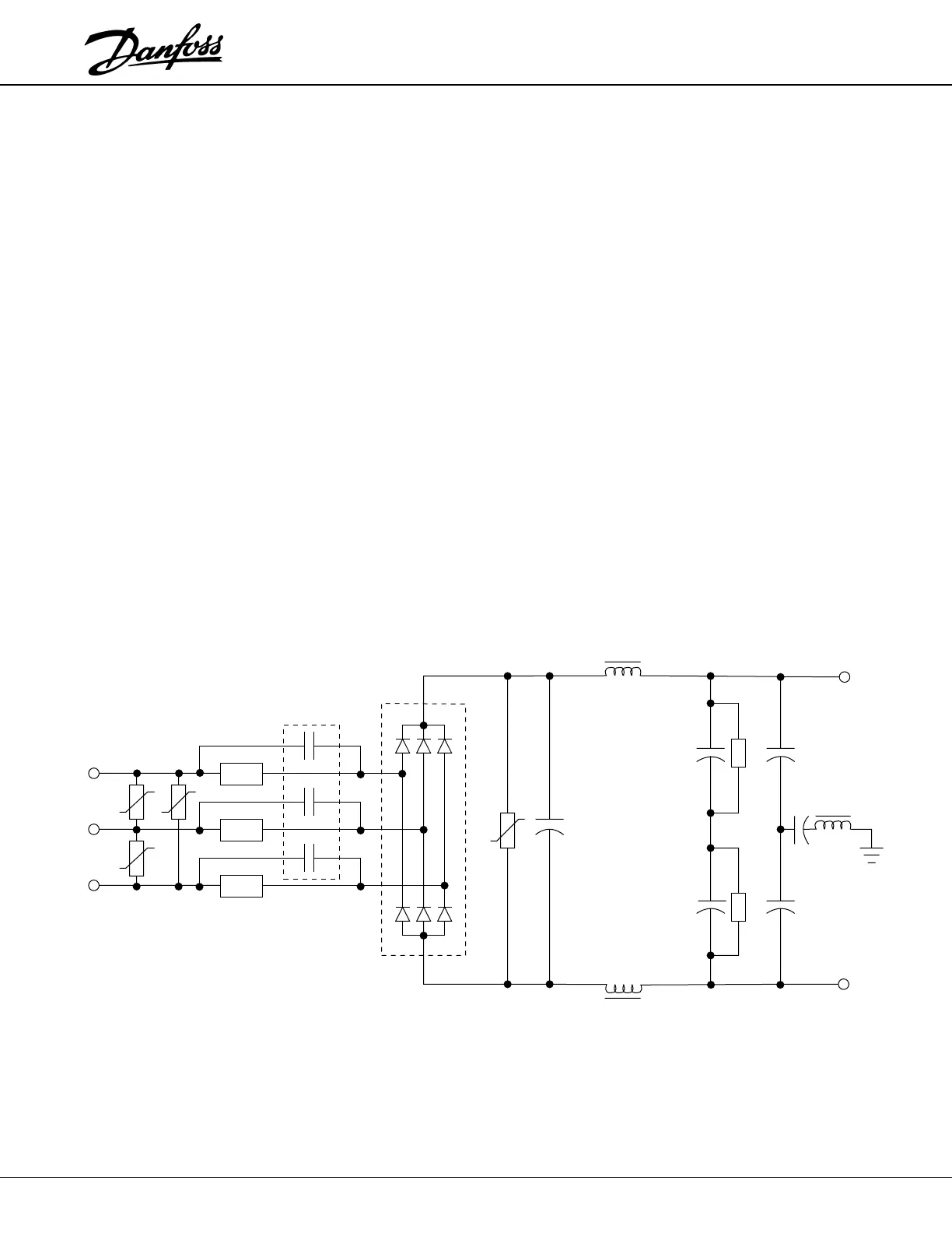
PTC resistors are placed in series with the inputs of the Rectifier Module to limit
the initial charge current of the DC Bus capacitors. The rectified line voltage is
then applied to the DC Bus filter. As the DC Bus voltage increases, the Interface
Card power supplies energize. As the power supplies stabilize, the Interface Card
sends a signal to the Relay Card to pull in the Bus Contactor. The Relay Card
energizes the contactor coil with a short burst of a high amplitude, full-wave rectified
voltage to pull in the Bus Contactor. The Relay Card then switches the Bus
Contactor coil voltage to a lower rectified holding voltage. As soon as the DC Bus
Contactor closes, the PTC resistors are effectively removed from the circuit and
the DC Bus Capacitors quickly finish charging.
1
Providing that the charging process proceeds normally, the Interface Card power
supplies will provide the Control Card with low voltage control power and the
Control Card display will indicate that the unit is ready for operation.
Following a run command and a speed reference, the Control Card delivers a
PWM signal (one per Phase) to the Interface Card. The Interface Card in turn
receives these three signals and creates six individual isolated gate drive pulses.
From here the gate pulses are fed directly to the Insulated Gate Bi-polar Transistor
(IGBT) output power devices. The IGBTs are switched on and off to develop the
PWM waveform which is ultimately delivered to the motor.
As the unit operates, the Interface Card monitors the unit's operational status.
Currents and voltages out of specified limits or excessive temperatures will result
in the Interface Card responding to the fault. The Interface Card sends the
appropriate fault message to the Control Card and in virtually all cases causes the
unit to trip. Section Two of this manual describes the fault messages and provides
direction in determining the cause and the solution for the fault.
Section One
1
The VLT 3511, 380/460V units have the Bus Contactor relay and PTC resistors
mounted on the ILD Card.
+VDC
–VDC
Bus
Capacitors
MOV
Bus Coil
Bus Coil
MOVs
Bus
Contactor
Rectifier
Module
PTCs
*
*
Only two PTC resistors
on some units
 Loading...