45
Wiring
• Serial Communications
– Need repeater (amplifier) after 31 drives attached together
– Dip switch settings 2 & 3 to OFF except for 2 bus ends
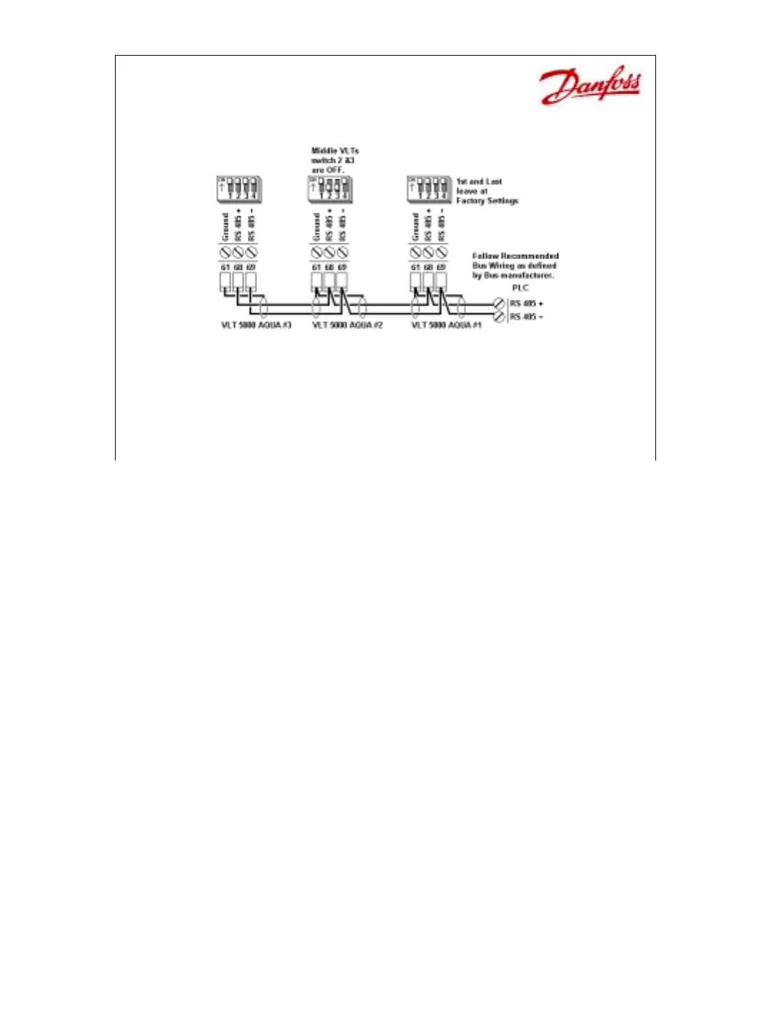
Serial Communications
This diagram shows how the serial communications is wired. Notice that it is an RS-
485 connection, which means that all the positive terminals (68) are wired together and all
the negatives (69) are wired together. These connections must be in a “Daisy Chain”
fashion which only has 2 ends. Star configurations should NOT be used. The address for
each drive is set in parameter 500, from address 1 to 126. The default address is #1. If
more than 31 drives are attached a repeater should be used to amplify the signal.
On the control card just above the serial communications plug, there is a DIP switch,
which is used to enable/disable the EOL (end of line) resistor. If one or 2 drives are attached
together, leave the DIP alone. Once a 3
rd
drive is added, the middle drive must have
switches 2 and 3 turned OFF, down, to remove the EOL resistor. If other drives are added,
all drive that are not on the 2 ends must have DIP switch settings 2 and 3 turned OFF.
 Loading...