Do you have a question about the DAS Aero 50 and is the answer not in the manual?
Highlights key warning symbols and general instructions for safe operation of the acoustic system.
Details precautions against moisture, liquids, improper placement, and outlines operating temperature and humidity limits.
Provides guidance on external wiring, parallel connections, rigging, and emphasizes professional servicing for internal components.
Instructions for cleaning the unit with a dry cloth and information on proper product disposal as electronic waste.
Details the product's adherence to European directives and harmonized standards for safety and electromagnetic compatibility.
Outlines the product warranty period, validity, repair process, and shipping responsibilities for claims.
Details the technical specifications, components, and intended applications of the aero 50 system.
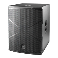
Provides visual representations and critical dimensions of the aero 50 loudspeaker enclosure.
Essential safety instructions and precautions for flying acoustic systems, covering general warnings and professional installation.
Details of rigging structures, adapters, and components like AX-AERO50, G1A50, G2A48, PL-50, and AX-COMBO12 for array assembly.
Information on load limits, safety factors, and maximum capacities for flying the acoustic system safely.
Instructions for transporting aero 50 and LX-218C cabinets using dolly panels and accessories.
Steps for simulating array setup, inspecting rigging hardware, and ensuring system integrity before installation.
Method for assembling acoustic arrays by connecting units sequentially, suitable for limited space.
Procedure for assembling and hoisting arrays using the PL-50 dolly platform for easier transport and connection.
Wiring diagram for a 16x aero 50 system with left and right LX-218C subwoofers and DSP-4080.
Wiring diagram for a 16x aero 50 system with 24x LX-218CA center cardioid subwoofers and DSP-4080.
Wiring diagram for a 24x aero 50 system with left and right LX-218C subwoofers and DSP-4080.
Wiring diagram for a 24x aero 50 system with 24x LX-218CA and 16x LX-218CRA center cardioid subwoofers and DSP-4080.
Wiring diagram for a 32x aero 50 system with left and right LX-218C subwoofers and DSP-4080.
| Nominal Coverage Angles | 90º x 50º |
|---|---|
| LF Driver | 12" (300 mm) |
| Amplifier Power LF | 500 W |
| Enclosure Material | Plywood |
| Weight | 32 kg |
| Woofer | 12" |
| Frequency Response | 55 Hz - 20 kHz |
| Amplifier Power HF | 100 W |
| Power Output | 600 W |