Table of Contents
Front and Rear Panel ........................................................................... 1
Remote Control.... ............................................................................... 2
Connections.........................................................................................3
First Time Installation........................................................................... 3
Troubleshooting...................................................................................8
Technical Specifications..................................................................... 10
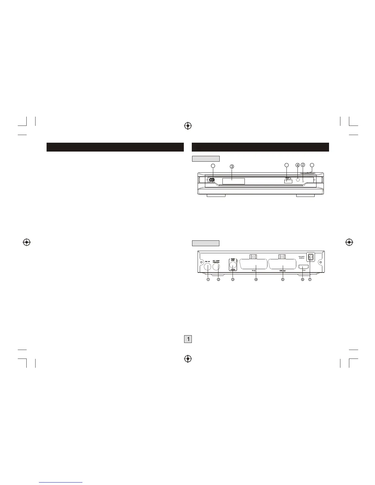
Front and Rear Panel
1. Front panel
1 POWER BUTTON: Used to turn on/off the main power supply.
2 STANDBY INDICATOR: Used to visually show power state of the set top
box, the LED will turn red if the set top box enter standby mode.
3
4 REMOTE CONTROL SENSOR: Used to receive the signal from the remote
control.
5 USB:
6 CHANNEL UP/DOWN: Used to change channels without using the remote
control.
LED DISPLAY WINDOW: Used to display channel number.
Data input from USB storage devices.
2. Rear panel
1 RF IN : This socket connects to your external aerial.
2 RF LOOP THROUGH: This socket will bypass the RF signal to either
your TV or another video system.
3 COAXIAL: This socket connects to a coaxial socket on your surround
sound system.
4 VCR SCART: This socket connects to either a DVD or other video
system.
5 TV SCART: This socket connects to your TV.
6 HDMI OUT This socket connects to HDMI in device.
7 MAINS CABLE: This is used to connect to your main power supply.
1
5
6
 Loading...