Connectors Specifications
User Manual 31
Encoder
Control rack back panel connector
Socket, M12, 8 pins female. Recommended encoder: Datalogic ENC58-S10-
XXXX-M12 (ENC58-S10-5000-M12). See “Starter Kit for Marking On the Fly
(MOF)” on page 71.
Figure 12: Encoder connector, female panel socket (front view)
PIN SIGNAL TYPE (*) DESCRIPTION
1 GND Ground Ground reference
2 VCC Power Output Auxiliary 24V DC power supply (750mA max)
3 ENC_A Digital input
Encoder HTL A channel signal
4 GND Ground Return signal for ENC_A
5 ENC_B Digital Input
Encoder HTL B channel signal
6 GND Ground Return signal for ENC_B
7 RESERVED -
DO NOT CONNECT
8 RESERVED - DO NOT CONNECT
BODY SHIELD Shield Shield
Table 4: Encoder connector pinout
(*) see “Input/Output specifications” on page 34
Photocell
Control rack back panel connector
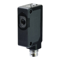
Socket, M12, 4 pins female. Recommended photocell: Datalogic S51-PA-5-B01-
PK; Datalogic S15-PA-5-B01-PK or equivalent. See “Starter Kit for Marking On
the Fly (MOF)” on page 71.
Figure 13:Photocell connector, female panel socket (front view)
PIN SIGNAL TYPE (*) DESCRIPTION
1 VCC Power Supply Auxiliary 24V DC power supply (120mA max)
2 RESERVED - DO NOT CONNECT
3 GND Ground
Ground reference
4 PHOTOCELL Digital input PNP photocell signal
Table 5: Photocell connector pinout
(*) see “Input/Output specifications” on page 34
 Loading...