- 2 -
Funktionsbeschreibung
Das Schaltgerät dient dem sicher-
heitsgerichteten Unterbrechen eines
Sicherheitsstromkreises. Nach Anlegen der
Versorgungsspannung leuchtet die LED
"Power". Das Gerät ist betriebsbereit, wenn
der Startkreis S12-S34 geschlossen wird
(automatischer Start) oder geschlossen und
wieder geöffnet wird (manueller Start).
• Eingangskreis geschlossen (z. B.
Lichtvorhang nicht unterbrochen):
Relais K1 und K2 gehen in Wirkstellung
und halten sich selbst. Die Statusanzeige
"CH. 1" und "CH. 2" für Kanal 1 und 2
leuchtet. Die Sicherheitskontakte 13-14,
23-24, 33-34 sind geschlossen, der
Hilfskontakt 41-42 ist geöffnet.
• Eingangskreis wird geöffnet (z. B.
Lichtvorhang unterbrochen):
Relais K1 und K2 fallen in die Ruhe-
stellung zurück. Die Statusanzeige "CH.
1" und "CH. 2" erlischt. Die Sicherheits-
kontakte 13-14, 23-24, 33-34 werden
redundant geöffnet, der Hilfskontakt 41-
42 geschlossen.
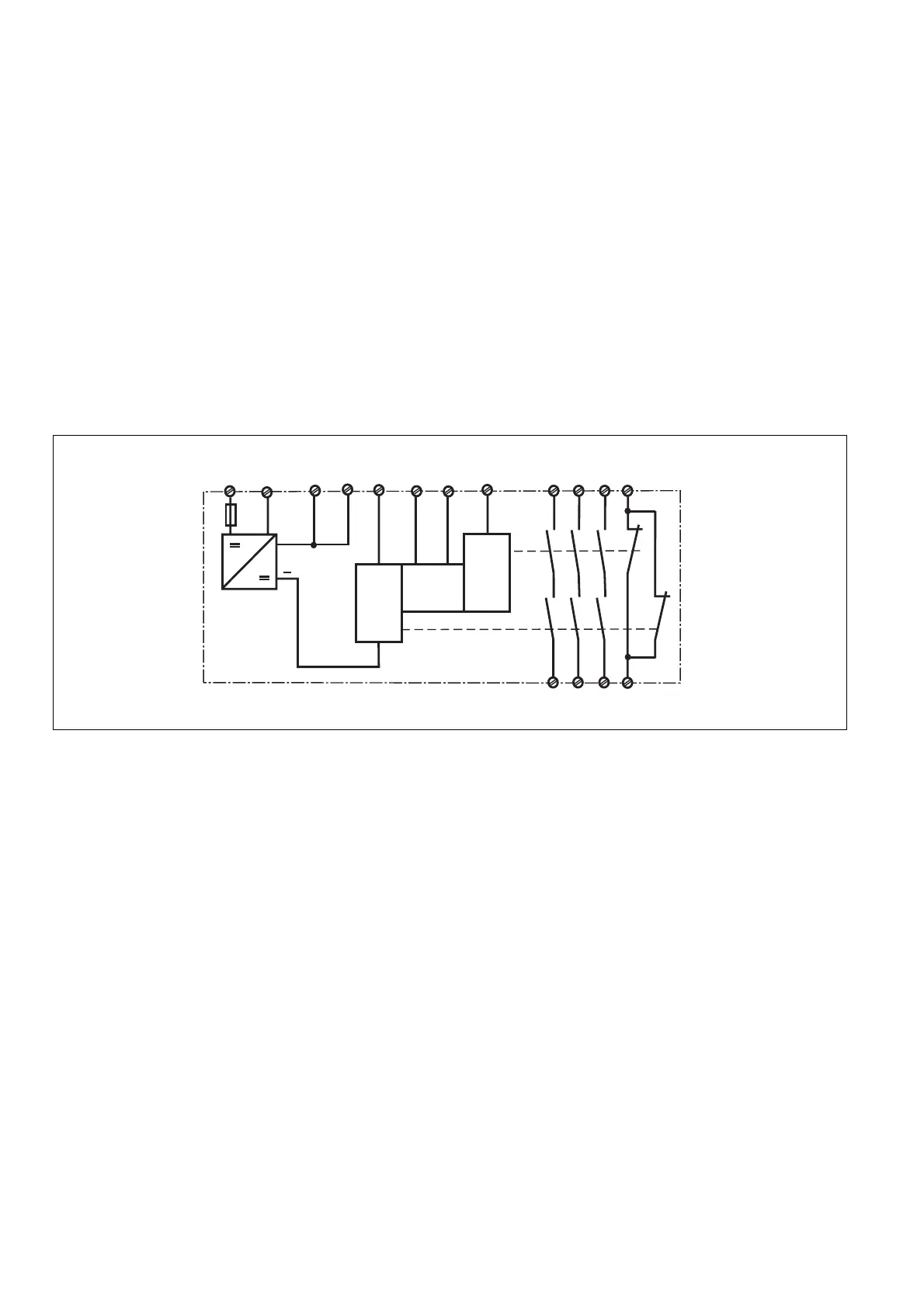
Fig. 1: Schema di collegamento interno/Innenschaltbild/Internal wiring diagram
Betriebsarten
• Zweikanaliger Betrieb ohne Querschluss-
erkennung: Redundanter Eingangskreis,
Kurzschlüsse und Erdschlüsse im
Tasterkreis werden erkannt.
• Automatischer Start: Gerät ist aktiv,
sobald der Eingangskreis geschlossen ist.
• Manueller Start: Gerät ist aktiv, wenn der
Startkreis S12-S34 geschlossen wird.
Dadurch ist ein automatischer Start des
Schaltgeräts nach Spannungsausfall und
-wiederkehr ausgeschlossen.
• Überwachter Start: Gerät ist nur aktiv,
wenn der Startkreis S12-S34 frühestens
200 ms nach Freigabe des Lichtvorhangs
geschlossen wird. Dadurch ist eine
automatische Aktivierung und Über-
brückung des Starttasters ausgeschlos-
sen.
• Kontaktvervielfachung und -verstärkung
durch Anschluss von externen Schützen
A1 (L+)
A2 (L-)
S12
S11
S34
13
14
K1
K2
23
24
S52
33
34
41
42
U
B
+
CH1
Start
Unit
CH2
Y37
Y36
Descrizione del funzionamento
Il dispositivo assicura l'interruzione di
sicurezza di un circuito elettrico di
sicurezza. Dopo l’immissione della tensione
di alimentazione il LED "Power" è acceso. Il
dispositivo è pronto per il funzionamento
quando il circuito di start S12-S34 è chiuso
(start automatico) oppure quando viene
chiuso e nuovamente aperto (start manuale).
• Il circuito di ingresso è chiuso (es.
barriere fotoelettriche non interrotte):
i relè K1 e K2 si eccitano e si
automantengono. Le visualizzazioni di
stato "CH. 1" e "CH. 2" per il canale 1 e 2
si illuminano. I contatti di sicurezza 13-14,
23-24, 33-34 sono chiusi, il contatto
ausiliario 41-42 è aperto.
• Il circuito di ingresso viene aperto (es.
barriere fotoelettriche interrotte):
i relè K1 e K2 si diseccitano. Le
visualizzazioni di stato "CH. 1" e "CH. 2"
si spengono. I contatti di sicurezza 13-14,
23-24, 33-34 vengono aperti in modo
ridondante, il contatto ausiliario 41-42
viene chiuso.
Modalità operative
• Modalità bicanale senza riconoscimento
del cortocircuito: un circuito di ingresso
ridondante, cortocircuiti e dispersioni a
terra nel circuito del pulsante vengono
riconosciuti.
• Start automatico: il dispositivo è attivo
non appena il circuito di ingresso viene
chiuso.
• Start manuale: l’unità è attiva, quando il
circuito di start S12-S34 è chiuso. In
questo modo si esclude uno start
automatico del relè dopo l’interruzione e il
ripristino dell’alimentazione di corrente.
• Start controllato: il dispositivo è attivo
solamente quando il circuito di start S12-
S34 viene chiuso con un anticipo di
almeno 200 ms dall’abilitazione della
barriera fotoelettrica. In tal modo si
esclude un’attivazione automatica e
un’esclusione del pulsante di start.
• Aumento del numero e della portata di
contatti tramite collegamento di relè
esterni
Function description
The relay provides a safety-related interrup-
tion of a safety circuit. When the operating
voltage is supplied, the "POWER" LED
illuminates. The unit is ready for operation
when the S12-S34 reset circuit is closed
(automatic reset) or closed and opened
again (manual reset).
• Input circuit closed (e.g. light curtain(s)
not interrupted):
Relays K1 and K2 energise and latch.
The status displays "CH. 1" and "CH. 2"
for channels 1 and 2 illuminate. Safety
contacts 13-14/23-24/33-34 are closed;
auxiliary contact 41-42 is open.
• Input circuit is opened (e.g. light curtain(s)
interrupted):
Relays K1 and K2 de-energise. The
status displays "CH. 1" and "CH. 2"
extinguish. Safety contacts 13-14/23-24/
33-34 are redundantly opened, with
auxiliary contact 41-42 closed.
Operating modes
• Dual-channel operation without detection
of shorts across contacts: Redundant
input circuit, short circuits and earth faults
in the pushbutton circuit are detected.
• Automatic reset: Unit is active as soon as
the input circuit is closed.
• Manual reset: Unit is active when reset
circuit S12-S34 is closed. Automatic
activation following a loss/return of supply
voltage is thereby prevented.
• Monitored reset: Unit is only active if reset
circuit S12-S34 closes no sooner than
200 ms after the light curtain has been
enabled. This eliminates the possibility of
the reset button being overridden,
triggering automatic activation.
• Increase in the number of safety contacts
available by connecting external contac-
tors
 Loading...
