INSTRUCTION MANUAL 21
CHAPTER 4
ELECTRICAL CONNECTIONS
PIN-OUT AND CONFIGURATION PIN CONNECTION
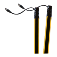
All electrical connections to the emitting and receiving units are made through some
particular cables; these are composed of a rectangular 18 pin connector on light curtain
side and M12 male connector(s) on the other side.
The Muting cable allows having on the receiving unit one M12 12-pole connector and
one M12
5-pole connector.
The Blanking cable allows having on the receiving unit one M12 12-pole connector.
The emitting unit has one M12 5-pole connector (both in Muting and Blanking mode).
The cables have to be connected on the bottom side of the light curtains (LEDs and push
but
ton side) by removing the white cap.
Figure 1 - Connections
Take care that the terminator cap (see "Accessories" on page 92) is connected on the top
side of the light curtains. If this connection mi
sses, Master and Slave units go in critical
Communication failure.
NOTE
Since the RX connections are different for M12 12-poles of Muting cable
and M12 12-poles of blanking cable, it's important to use the correct cable
for each configuration (connector with two M12 with the Muting configura-
tion and connector with one M12 with the blanking configuration).
 Loading...