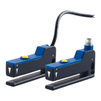
SR23
INSTRUCTION MANUAL
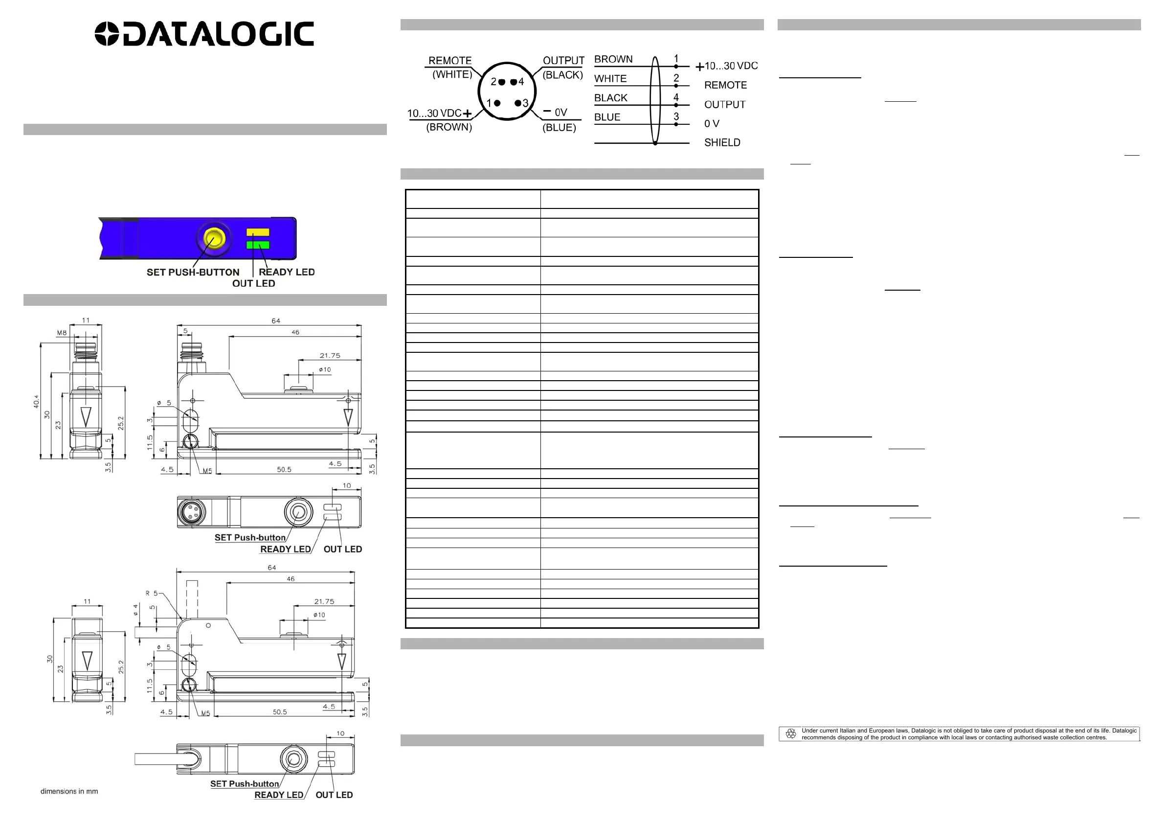
CONTROLS
OUTPUT LED (YELLOW)
The yellow LED ON indicates output activation.
READY LED (green)
The green LED continuously ON indicates a normal operating condition. Refer to the “SETTING”
paragraph for the correct setting phase indications.
SET PUSH-BUTTON
Press SET push-button to activate acquisition.
DIMENSIONS
M8 CONNECTOR VERSION
CABLE VERSION
CONNECTIONS
M8 connector
(Connector view from external sensor side)
The thread allows connection to earth
Cable
TECHNICAL DATA
Power supply: 10 … 30 VDC;
reverse polarity protection
Ripple: 2 Vpp max.
Consumption
(output current excluded):
30 mA max.
Outputs: NPN and PNP according to the model;
pull up/down resistance= 33 K
Input / Remote: 10… 30 VDC
Current output:
100 mA max.
short-circuit protection
Capacitive load: ≤ 0.2µF
Output saturation voltage: 2 V max.
(values at maximum output current)
Response time: 40 µs max.
Switching frequency: 12 kHz max.
Tape speed during acquisition: ≤ 20m/min (30cm/s)
Humidity: 35 … 85% rH non condensing
Indicators: READY LED (GREEN)
OUT LED (YELLOW)
Setting: SET push-button
Data retention: EEPROM non volatile memory
Operating temperature: -20 … 55°C
Storage temperature: -20 … 70°C
Dielectric strength: 500 VAC, 1 min between electronic parts and housing
Insulating resistance:
>20 M, 500 VDC between electronic parts and housing
UL requirements:
Class 2 power supply according to UL 508-Type 1 Enclosure
minimum distance between the “Proximity Switch Metal
Enclosure” and any “External uninsulated live part” shall be
at least 12.7 mm
Emission frequency: 50 kHz frequency modulated light
Emission type: INFRARED 850 nm
Ambient light rejection: according to EN 60947-5-2
Vibrations:
0.5 mm amplitude, 10 … 55 Hz frequency,
for every axis (EN60068-2-6)
Shock resistance: 11 ms (30 G) 6 shocks per every axis (EN60068-2-27)
Slot width: 5 mm
Slot depth: 50 mm
Limits of detectable object:
Label width: ≥ 2 mm
Gap width: ≥ 2 mm
Housing material: Zinc alloy
Lens material: PBT
Mechanical protection: PC
Connections: IP65
Weight: 2m cable / M8 4-pole connector
Housing material: 85 g. cable vers. / 46 g. M8 connector vers.
REMOTE FUNCTION AND PUSH-BUTTON BLOCKING
Using the REMOTE input, it is possible to perform the same SET check outside the sensor.
When the REMOTE wire is connected to +Vdc, it is as if the SET push-button was pressed.
Upon sensor switch-on, if the REMOTE wire is connected to +VDC, the block function is activated so
the SET push-button is no longer active.
To disable push-button block, switch sensor off and back on with the REMOTE wire disconnected or
connected to 0 V.
After push-button block, it is possible to program the device using the REMOTE input.
EARTH CONNECTION
You can connect to the earth in the following ways:
1. SR23 M8 conn. & Cable: by the M5 threaded hole on the body (preferential).
2. SR23 M8 conn.: by the use of a shielded cable with the shield connected to earth; use a shielded
cable with the shield connected to the threaded nut on the cable.
3. SR23 cable: by the connection of the cable shield itself.
SETTING
The device is factory-set with output active on support-label (background).
This setting can be changed as described below.
DYNAMIC acquisition:
A) Insert labels into sensor slot.
B) Press SET push-button for 1 second until the READY green LED switches OFF.
If the OUT yellow LED is ON, it will turn off together with the READY green LED.
C) Release SET push-button.
At this stage, switching output is frozen on the last valid status before acquisition.
D) The READY green LED blinks slowly, thereby indicating acquisition in progress.
E) Slide the labels through the sensor, at a maximum speed of 20 m/min (30 cm/s), until at least 3...8
labels get through the sensor.
F) Briefly press SET push-button to end acquisition stage: 3 blinks of the READY green LED indicate
correct acquisition.
In case of unsuccessful acquisition, the READY green LED blinks quickly.
If this is the case, briefly press SET push-button to go back to the beginning of acquisition stage and
repeat the process.
If error persists, label-to-background contrast might be not sufficient to obtain a correct acquisition
result.
STATIC acquisition:
A) Place the object to detect (the support or the label) into the sensor slot.
If necessary, remove one or more labels to help positioning on the support.
B) Press SET push-button for 3 seconds until the OUT yellow LED blinks.
When you press SET, if the OUT yellow LED is on, it will turn off in 1 second.
At this stage, switching output is frozen on the last valid status before acquisition.
C) Release SET push-button; the sensor acquires the target.
The OUT yellow LED blinks slowly.
D) Place the object to ignore (the support or the label) into the sensor slot.
E) Briefly press SET push-button; the sensor acquires the target: 3 blinks of the READY green LED
indicate correct acquisition.
In case of unsuccessful acquisition, the READY green LED blinks quickly.
If this is the case, briefly press SET push-button to go back to the beginning of acquisition stage and
repeat the process.
If error persists, label-to-background contrast might be not sufficient to obtain a correct acquisition
result.
Reversing Output status:
A) Press SET push-button for 7 seconds until both READY green LED and OUT yellow LED blink at
the same time.
B) Release SET push-button.
Output status is now reversed compared to previous conditions.
This setting is saved to the device.
Restoring the device factory settings:
A) Press SET push-button for 12 seconds until both READY green LED and OUT yellow LED blink
quickly.
B) Release SET push-button.
The device factory settings are now restored.
Output short-circuit warning:
In case of short-circuit of the PNP or NPN output, the READY green LED and OUT yellow LED blink
quickly and alternatively.
The sensors are NOT safety devices, and so MUST NOT be used in the safety control
of the machines where installed.
Datalogic S.r.l.
Via S. Vitalino 13 - 40012 Calderara di Reno - Italy
Tel: +39 051 3147011 - Fax: +39 051 3147205 - www.datalogic.com
Helpful links at www.datalogic.com: Contact Us, Terms and Conditions, Support.
The warranty period for this product is 36 months. See General Terms and Conditions of Sales for further details.
Under current Italian and European laws, Datalogic is not obliged to take care of product disposal at the end of its life. Datalogic
recommends disposing of the product in compliance with local laws or contacting authorised waste collection centres.
© 2014 - 2017 Datalogic S.p.A. and/or its affiliates ALL RIGHTS RESERVED. Without limiting the rights under copyright, no part of this
documentation may be reproduced, stored in or introduced into a retrieval system, or transmitted in any form or by any means, or for any
purpose, without the express written permission of Datalogic S.p.A. and/or its affiliates. Datalogic and the Datalogic logo are registered
trademarks of Datalogic S.p.A. in many countries, including the U.S.A. and the E.U. All other trademarks and brands are property of their
respective owners. Datalogic reserves the right to make modifications and improvements without prior notification.
821002822 Rev.B
 Loading...