SETTING OF THE 2 THRESHOLDS
The sensor setting is effected placing the object to detect directly in front of the sensor following the
procedure given below:
z push-button pressed { push-button not pressed
LED on LED off
- Obect detection at OFF/ON output switching
- Position the object inside the measurement area to define the measurement value (depending
on the operating mode used) corresponding to the OFF/ON switching of the digital output.
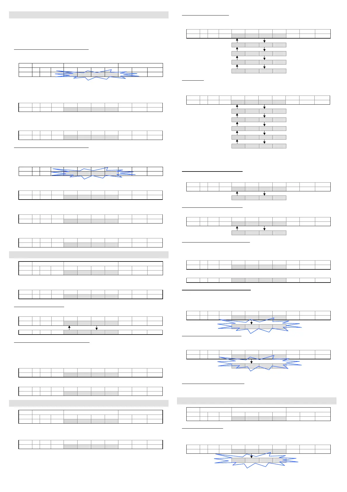
Display Keyboard
OUT A M1 M2 Dig1 Dig2 Dig3 Dig4 + SET -
4 5 0
{ z {
- Press the SET push-button for at least 2s.
- The detected value for the first switching threshold appears (4Hz blinking until the SET push-
button is released).
- The value acquired can be changed using the +/- push-buttons.
OUT A M1 M2 Dig1 Dig2 Dig3 Dig4 + SET -
4 5 0
z { z
- The units change if these push-buttons are pressed repeatedly, the tens if kept pressed.
- Press the SET push-button again for at least 0.5 s. to end the detection phase of the first
switching threshold.
OUT A M1 M2 Dig1 Dig2 Dig3 Dig4 + SET -
4 5 0
{ z {
- Obect detection at ON/OFF output switching
- Position the object inside the measurement area to define the measurement value (depending on
the operating mode used) corresponding to the ON/OFF switching of the digital output.
-
The detected value for the second switching threshold appears.
-
OUT A M1 M2 Dig1 Dig2 Dig3 Dig4 + SET -
6 0 0
{ z {
- The present value appears (4Hz blinking).
- Press the SET push-button again for at least 0.5 s. to detect the second switching threshold.
OUT A M1 M2 Dig1 Dig2 Dig3 Dig4 + SET -
6 0 0
{ z {
- The detected value for the second switching threshold appears.
- The value acquired can be changed using the +/- push-buttons.
OUT A M1 M2 Dig1 Dig2 Dig3 Dig4 + SET -
6 0 0
z { z
- The units change if these push-buttons are pressed repeatedly, the tens if kept pressed.
- Press the SET push-button again for at least 0.5 s. to end the detection phase.
OUT A M1 M2 Dig1 Dig2 Dig3 Dig4 + SET -
6 0 0
{ z {
SWITCHING THRESHOLD ADJUSTMENT
Display Keyboard
OUT A M1 M2 Dig1 Dig2 Dig3 Dig4 + SET -
0 4 5 0
z { z
- Press one of the +/- push-buttons for at least 2 s.
- The “tH-1” message appears.
OUT A M1 M2 Dig1 Dig2 Dig3 Dig4 + SET -
t H - 1
{ { {
- Switching threshold selection
- Use the +/- push-buttons to select the switching threshold.
OUT A M1 M2 Dig1 Dig2 Dig3 Dig4 + SET -
t H - 1
z { z
t H - 2
z { z
- Adjustment phase of the switching threshold
- Press the SET push-button for at least 0.5 s.
- The previously detected value appears.
- The value can be changed using the +/- push-buttons.
- The units change if these push-buttons are pressed repeatedly, the tens if kept pressed.
OUT A M1 M2 Dig1 Dig2 Dig3 Dig4 + SET -
0 6 0 0
z { z
- Press the SET push-button again for at least 0.5 s. to end the adjustment phase.
OUT A M1 M2 Dig1 Dig2 Dig3 Dig4 + SET -
0 4 5 0
{ z {
SETTING OF THE PARAMETERS
Display Keyboard
OUT A M1 M2 Dig1 Dig2 Dig3 Dig4 + SET -
4 5 0
{ z {
Press the SET push-button for at least 6s to enter into the parameter setting mode.
The "MEnu" message appears.
OUT A M1 M2 Dig1 Dig2 Dig3 Dig4 + SET -
M E n u
{ { {
- Pressing the + and –push-buttons the user can run up and down the menu, reading the
following messages.
- Functioning mode selection
- At each pressure on the SET push-button the user can run through the options of the selected
level.
OUT A M1 M2 Dig1 Dig2 Dig3 Dig4 + SET -
E n d
z { z
b E G
{ z {
c E n t
{ z {
W I d t
{ z {
A r E A
{ z {
- Delay setting
- At each pressure on the SET push-button the user can run through the options of the selected
level.
OUT A M1 M2 Dig1 Dig2 Dig3 Dig4 + SET -
d - 0 0
z { z
d - 0 5
{ z {
d - 1 0
{ z {
d - 2 0
{ z {
d - 3 0
{ z {
d - 4 0
{ z {
- The setting of the delay value is in common to both outputs.
When the delay value set is different from zero, the outputs will remain active for a minimum
time equal to the number of milliseconds visualised on the display.
- Visualisation of the threshold 1 data
- Pressing the SET push-button the value of the threshold 1 appears.
OUT A M1 M2 Dig1 Dig2 Dig3 Dig4 + SET -
t H - 1
z { z
THRESHOLD 0 4 5 0
{ z {
- Visualisation of the threshold 2 data
- Pressing the SET push-button the value of the threshold 2 appears.
OUT A M1 M2 Dig1 Dig2 Dig3 Dig4 + SET -
t H - 2
z { z
THRESHOLD 6 0 0
{ z {
- Visualsation of the operating area status
- Pressing the SET push-button the operating area status. More precisely; if “FULL” the operating
area is complete, if “REDU“ the acquired area is not complete, but presents some zones that do
not have to be detected .
OUT A M1 M2 Dig1 Dig2 Dig3 Dig4 + SET -
F U L L
z { z
or
r E d U
z { z
- Reset of the sensor default configuration
- Pressing the SET push-button (the “RESE” message blinks for 2s, 4Hz) the default configuration
is re-set and the user exits from the menu, returning to the normal mode. The default
configuration is: “beg object” operating mode, delay 0, Th1 switching threshold = 100, Th2 =
200.
OUT A M1 M2 Dig1 Dig2 Dig3 Dig4 + SET -
r E S E
z { z
r E S E
{ z {
- Memorisation of the parameters set
- Pressing the SET push-button (the “SAVE” message blinks for 2s, 4Hz) all the modified values
are memorised and the user exits form the menu,returning to the normal mode.
OUT A M1 M2 Dig1 Dig2 Dig3 Dig4 + SET -
S A V E
z { z
S A V E
{ z {
- Press one of the +/- push-buttons the user can return to the setting menu.
- Exit from the parameter setting menu
After 10s inactivity of the sensor push-buttons, the sensor returns to the normal operating mode
visualising the distance.
ADVANCED FUNCTIONS
Display Keyboard
OUT A M1 M2 Dig1 Dig2 Dig3 Dig4 + SET -
0 4 5 0
z { z
- Operating area selection
- Press contemporarily the + and – push-buttons for at least 2s.
- The “W_Ar” message appears.
OUT A M1 M2 Dig1 Dig2 Dig3 Dig4 + SET -
W _ A r
{ { {
W _ A r
{ z {
- The operating area configuration is memorised when the push-buttons are released (the W_Ar
blinks for 2s, 4Hz) and the sensor returns to the normal mode.
 Loading...