Do you have a question about the Datex-Ohmeda Engstrom Carestation and is the answer not in the manual?
Details the components and scope covered in this service manual for the Engström Carestation.
Highlights the necessity of the User's Reference manual for service personnel to expedite repairs.
Explains typographical conventions for keys, menu selections, messages, and headings.
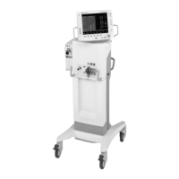
Provides a general overview of the Engström Carestation as a critical care ventilator.
Details the front view of the Engström Carestation and identifies its main components.
Describes the various controls and indicators found on the display unit of the Engström Carestation.
Explains the normal screen view of the ventilator display, including its fields and settings.
Provides a step-by-step guide on navigating and interacting with the ventilator's menu system.
Defines common symbols used in the manual and on the Engström Carestation equipment.
Details the pneumatic system, gas requirements, and flow channels of the Engström Carestation.
Explains the function of the primary gas inlet, filters, and pressure transducers.
Describes the solenoid-powered exhalation valve, pressure transducer, and flow transducer.
Covers zeroing valves, auxiliary pressure channels, and the electronic micropump nebulizer.
Outlines the electrical system, including processor boards and analog boards in the Engström Carestation.
Details the connections available on the Display Unit (DU) and High Performance Display Unit (HPDU).
Explains the various digital and serial communication channels used within the Engström Carestation.
Describes the VCB's role in sensor data acquisition, actuator control, and system communication.
Details the VMB's monitoring capabilities, safety parameter acquisition, and communication links.
Explains the PMB's role in power selection, battery charging, and system shutdown sequences.
Lists other electronic items in the EC, including power supplies and backup batteries.
Describes the motherboard's role in providing backplane connectivity and external connectors.
Details the optional module assembly and the Monitoring Interface Board (MIB).
Ensures the system is in proper condition before performing any tests.
Guides through running the automated checkout and interpreting results.
Details the steps for testing the display's backlight functionality.
Describes how to test the system's behavior during a power failure.
Outlines the procedures for verifying electrical safety compliance.
Describes the hierarchical structure of the Service and Installation menus.
Details how to access the Install/Service menu using the super-user password.
Explains how to configure graphical trend pages and select trend types.
Covers settings for colors, units, alarm limits, and time/date.
Details settings for timing, flow, and modes with backup ventilation.
Covers settings for value calculations and CO2 humidity compensation.
Explains how to select and manage default patient types and settings.
Lists the factory default settings for parameters and alarm limits for different patient types.
Describes the calibration procedures available, including O2 FCV, Air FCV, and Exhalation Valve.
Details the options available within the Service menu, such as configuration and service logs.
Covers settings for decimal marker, language, units, and altitude.
Explains how to enable software options using key codes and lists.
Describes the process of installing software options using an options card.
Explains how to save and copy system configurations to and from a memory card.
Details how to access and review error, event, and alarm histories.
Shows how to view system information, including software and hardware versions.
Provides instructions for resetting feature option key codes and performing related tasks.
Covers periodic calibration of O2 flow valve, Air flow valves, and Exhalation valve.
Step-by-step guide for performing O2 FCV, Air FCV, and Exhalation Valve calibrations.
Details service level tests requiring the EC Service Application on a PC.
Instructions for connecting a PC and starting the Service Application.
Describes the necessary connections for performing service level tests.
Procedure for cleaning debris from the vent engine after servicing.
Steps to check and adjust the output pressure of the Air and O2 regulators.
Procedure for performing the first low pressure leak test on the vent engine.
Tests the vent engine for leaks under high O2 pressure conditions.
Tests the vent engine for leaks under high Air pressure conditions.
Procedure for calibrating the inspiratory, expiratory, and auxiliary pressure transducers.
Checks the functionality of the free-breathing valve using negative pressure.
Tests the operation of the inspiratory effort valve using a squeeze bulb.
Checks the operation of the auxiliary pressure relief valve using a manometer.
Tests the mechanical over-pressure valve by injecting air into the system.
Provides a checklist for initial installation and setup of the Engström Carestation.
Outlines the planned maintenance tasks required at 12, 48, and 60-month intervals.
Details the maintenance procedures for the JunAir EVair03 compressor.
Lists validated cleaning and disinfection agents for various components.
Describes how to test the capacity and viability of the system's backup batteries.
Guides on troubleshooting specific failures identified during the checkout process.
Provides steps to locate and resolve leaks within the vent engine system.
Explains POST messages and their corresponding troubleshooting actions.
Specific troubleshooting for POST messages on the High Performance Display Unit.
Addresses common problems with the HPDU, such as boot failures and fan noise.
A comprehensive chart for identifying and resolving alarm messages.
Helps troubleshoot messages encountered during service application tests or calibrations.
Introduction to the EC Service Application for diagnostics and software management.
Details the main menu options and how to view system information.
Provides access to power supply diagnostics for various circuit boards.
Detailed diagnostics for the power controller, including voltage and battery status.
Lists the power diagnostics available for the Display Unit.
Guides on performing diagnostics for display components like LEDs, speaker, and backlight.
Access to error, alarm, event logs, revision logs, and compatibility tables.
Displays chronological entries for every software download to the system.
Provides log entries for software downloads completed using the PC card.
Instructions for downloading new or all subsystem software.
Details on using the PC-based service application for communication.
Covers diagnostics and calibration procedures for the Ventilator Control Board (VCB).
Shows temperature and flow data from the Sensirion flow sensors.
Displays the status of various input signals for the VCB.
Lists measured items from the VCB and their acceptable ranges.
Details the controls for VCB outputs, including their function and default state.
Lists various calibrations and tests available for the VCB.
Provides lists of counts, flows, and zero offsets related to the Neonatal Flow Sensor.
Menu used by manufacturing for PEEP stability checks.
Instructions for logging checkout results to a file using the PC Service Application.
Procedure for logging calibration results to a file using the PC Service Application.
Introduction to the VMB diagnostics pages.
Lists measured items from the VMB and their acceptable ranges.
Details the controls for VMB outputs, including their function and default state.
Shows reported values for Expiratory Flow and O2 concentration from the VMB.
Procedure for calibrating the barometric pressure transducer.
Details software version and sensor data for the acutronic sensor.
Notes that EEPROM is used by manufacturing only.
Important precautions before replacing circuit boards in the Engström Carestation.
Instructions for downloading software after replacing specific circuit boards.
Details necessary calibrations after replacing VMB or VCB.
Procedure for safely bleeding gas pressure before disconnecting fittings.
Explains how to access internal components by sliding out the chassis.
Step-by-step instructions for removing the main chassis from the unit's housing.
Procedure for detaching the Vent Engine assembly from the main chassis.
Guidance on replacing major components mounted directly on the chassis.
Instructions and warnings for replacing components within the vent engine assembly.
Detailed steps for replacing the inspiratory valve assembly (Part No. 1505-8502-000).
Procedure for replacing the free breathing valve (Part No. 0211-1454-100).
Instructions for replacing the entire Vent Engine assembly.
Steps for replacing sub-assembly components of the Vent Engine.
General procedures for servicing the standard Display Unit (DU).
Step-by-step guide to detach the Display Unit from its pivot arm.
Instructions for disassembling the DU, including accessing internal components.
Procedure for replacing the CPU board within the Display Unit.
Detailed steps for removing and replacing the LCD display module.
Instructions for replacing the backlight assembly and inverters.
Procedure for replacing the inverter boards associated with the LCD backlight.
Steps for replacing the front enclosure, window, membrane switches, or keypads.
General procedures for servicing the High Performance Display Unit (HPDU).
Step-by-step guide to detach the HPDU from its pivot arm.
Instructions for disassembling the HPDU, including accessing internal components.
Procedure for replacing the CPU fan on the HPDU's CPU board.
Detailed steps for replacing the CPU board in the High Performance Display Unit.
Instructions for replacing the LCD display module in the HPDU.
Procedure for replacing the backlight assembly and inverters in the HPDU.
Steps for replacing the inverter boards for the HPDU backlight.
Guidance on replacing the front enclosure, window, or membrane switches on the HPDU.
Instructions for adjusting the display arm pivots and bearing for optimal viewing.
Steps for adjusting the upper pivot point of the display arm.
Steps for adjusting the lower pivot point of the display arm.
Procedure for adjusting the arm bearing for smooth side-to-side movement.
Instructions for safely removing the air compressor from the cart for service.
Guidance on attaching Key/BID and Feature labels to the Engström Carestation.
Lists essential service tools, software, and cables for Engström Carestation maintenance.
Details manual shut-off valves, adapters, and filter bodies for gas lines.
Lists specialized tools such as remote display cables and alignment tools.
Describes the components included in the leak test device kit.
| Brand | Datex-Ohmeda |
|---|---|
| Model | Engstrom Carestation |
| Category | Respiratory Product |
| Language | English |