15
SECTION 3
TECHNICAL
DESCRIPTION
3.1
INTRODUCTION
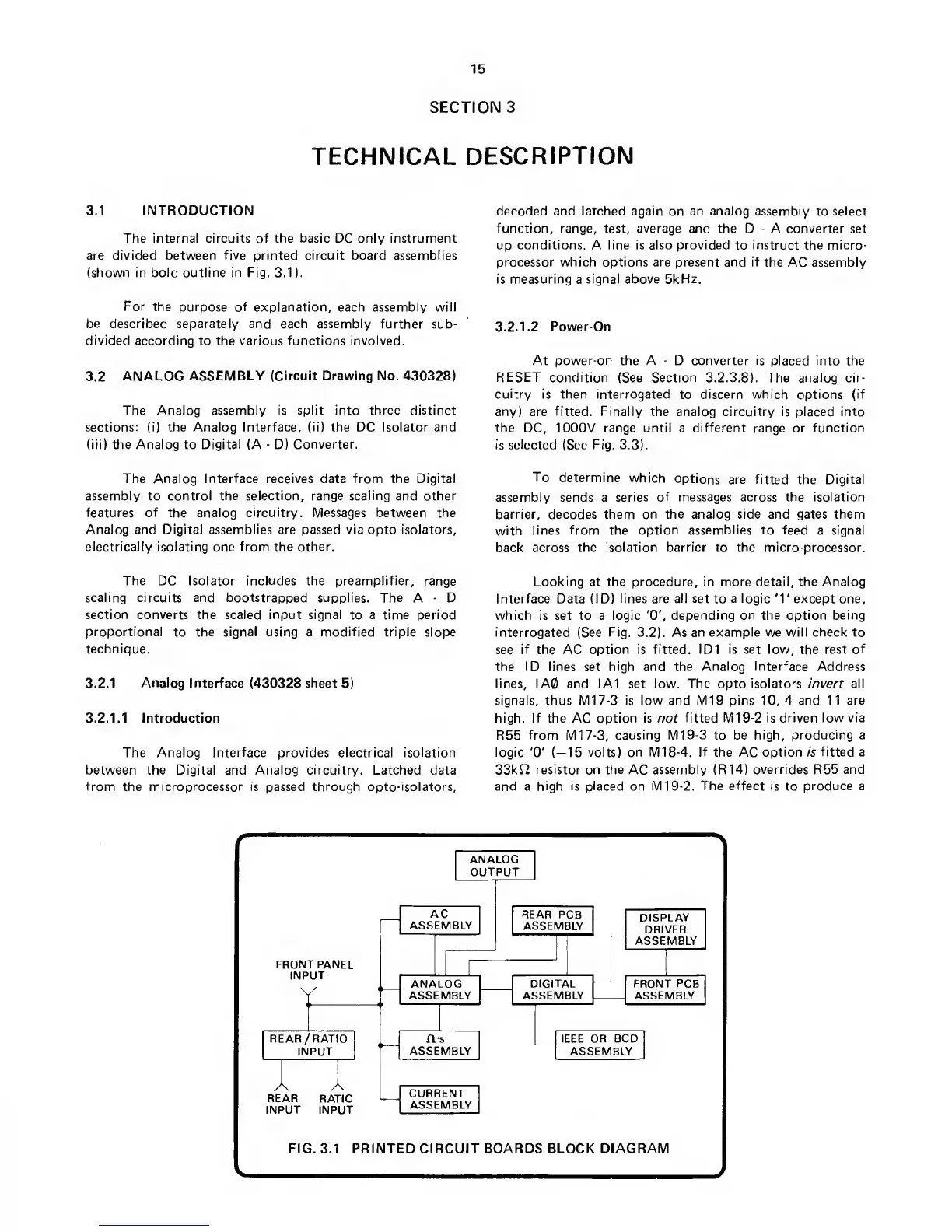
The internal circuits of the basic DC only instrument
are divided between
five printed circuit
board assemblies
(shown in bold outline in Fig.
3.1).
For
the purpose
of explanation, each assembly will
be
described separately and each assembly
further sub-
divided according
to the
various functions involved.
3.2
ANALOG
ASSEMBLY (Circuit Drawing No.
430328)
The Analog assembly is
split
into three distinct
sections: (i) the Analog Interface,
(ii)
the DC Isolator and
(ill) the Analog to
Digital
(A
-
D)
Converter.
The Analog Interface receives data from the Digital
assembly to control
the selection, range scaling
and
other
features of
the analog
circuitry. Messages
between the
Analog and Digital assemblies are passed via opto-isolators,
electrically isolating one from the other.
The DC Isolator includes the preamplifier,
range
scaling circuits and bootstrapped supplies. The
A
-
D
section converts the scaled input signal
to
a time period
proportional
to
the signal using
a
modified triple
slope
technique.
3.2.1
Analog
Interface
(430328
sheet
5)
3.2.1.
1
Introduction
The Analog Interface provides electrical isolation
between the Digital and
Analog circuitry.
Latched data
from
the
microprocessor is
passed
through
opto-isolators,
decoded and latched
again
on an analog assembly
to
select
function, range, test, average and the
D
-
A
converter
set
up conditions. A line is also provided
to
instruct the micro-
processor which options are present and if
the AC assembly
is measuring
a
signal above 5kHz.
3. 2.
1.2
Power-On
At
power-on
the A
-
D converter is placed into the
RESET condition
(See Section 3. 2. 3.
8).
The analog cir-
cuitry
is then interrogated
to
discern which
options
(if
any) are
fitted. Finally
the analog circuitry is placed into
the DC,
1000V
range until
a
different
range
or function
is
selected
(See Fig.
3.3).
To
determine
which
options
are fitted
the
Digital
assembly sends a
series of messages across the isolation
barrier, decodes them on the analog side and gates them
with
lines
from
the
option assemblies to feed
a signal
back
across the isolation barrier to the micro-processor.
Looking
at
the procedure, in more detail, the Analog
Interface
Data (ID)
lines
are
all set
to
a
logic '1'except one,
which is set to a logic 'O',
depending on the option being
interrogated
(See
Fig.
3.2). As
an example we will check to
see
if
the AC option
is fitted. ID1 is set low,
the
rest of
the ID lines set
high
and
the Analog Interface Address
lines, IA0 and IA1
set
low. The opto-isolators invert all
signals, thus M17-3 is low and M19
pins
10,
4
and
11 are
high. If the
AC
option is not
fitted
M19-2
is driven low via
R55
from
Ml
7-3, causing M19-3
to be high, producing
a
logic
'0'
(—15
volts) on
M18-4.
If
the AC
option
/s
fitted a
33kI2 resistor on
the
AC
assembly
(R14)
overrides
R55
and
and a
high is placed
on Ml
9-2.
The effect
is to
produce a
f
\
y
FIG.
3.1
PRINTED CIRCUIT BOARDS BLOCK DIAGRAM
J
 Loading...