412
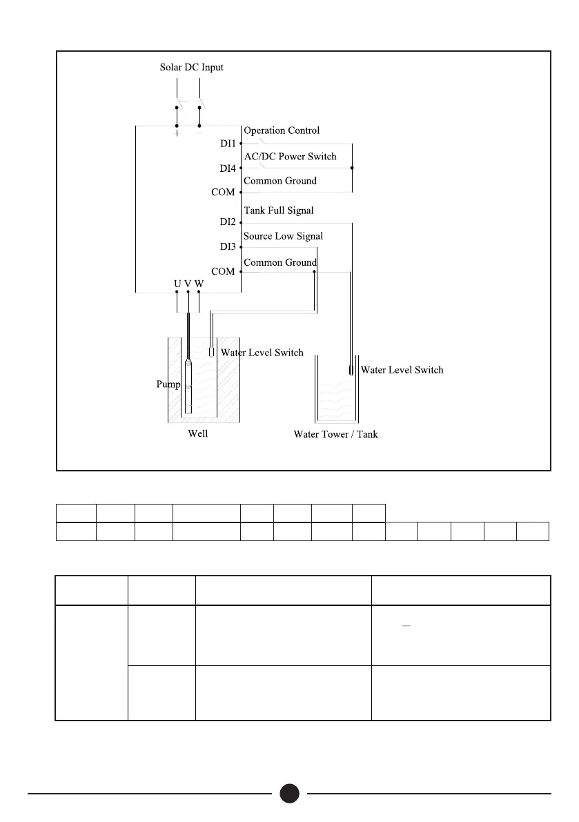
Ÿ The basic wiring of Sunverter B is shown in Fig.3
Fig 3: Standard Wiring Diagram
Control Terminal Description
PE
485+ 485-
0~10V/5V
AIN
GND
COM
D13
+24V
PW COM
DI1
DI2
COM
D14
D15 T1A T1B T1C T2A T2C
Control Board Terminal Function Description
+24 V
24V + 10%, isolated from GND
internally
Maximum output current: 200 mA
Type
Terminal
Label
Function Description Technical Specications
S w i t c h
Signal Input
Terminal
+24 V power supply
PW
Connected to +24 V terminal by
default
External power input terminal
(power supply of switch signal
input terminal)
PV
Disconnect
Sunverter B
Solar Pumping
Inverter
Note: For Single Phase
m o d e l s U & V
terminals of inverter
should be connected
to L&N terminals of
single phase pump
with capacitors or via
capacitor control box.
 Loading...