detected at time t
3
, whereupon the "–PEAK" channel will track
down to the second, lower peak (P
2
), etc.
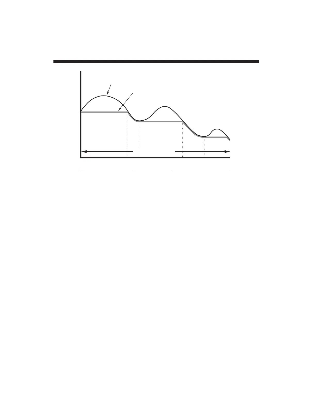
Fig. 18 shows how to
reset
the "–PEAK" channel to capture
successively higher-valued signal minima. Until time t
1
(when the
"–PEAK HOLD" mode begins), Channel 3 has been continuously
"tracking" the analog input, as shown. From time t
1
to time t
2
, the
input is continuously falling, and so Channel 3 appears to be
continuing to track it. At time t
2
, however, the input signal reaches
its first true minimum since time t
1
. This "negative" peak (P
1
) is
"captured" and held until Channel 3 is
momentarily
returned to
"TRACK" mode at time t
2
. The second, higher-valued minimum
(P
2
) can now be captured at time t
4
, etc.
4. Connection of Logic Inputs
A logic input to the 4077's rear-panel "+PK IN" or "–PK IN" terminal
may be applied by means of an external switch or an active TTL
source, using the connections shown in Fig. 19. The switch-
closure method does not require an external logic reference supply.
Analog Peak Capture App. G
G.6

 Loading...