Ceiling/wall models 28, 30, 31, 34, 38, 52 and 53
1. Loosen the M8 screws which attach the
suspension brackets to the heater casing and
remove the brackets.
2. Position and fix the suspension brackets to
the ceiling or wall; see Diagram 19 on page
15.
3. Lift the heater into position and secure the
heater to the suspension brackets by the four
M8 screws. (If applicable, fit external
weatherproof louvres for model 53).
4. Connect pipework to the coil as described in
Pipework Connections
below.
5. Wire up as detailed in
Electrical Connections
and Controls
on page 7.
6. If supplied, fit the adjustable (type 2) low
temperature cut-out thermostat to the LTHW
flow pipe.
7. After filling the system, check for leaks (see
Commissioning
on page 7).
8. Replace all components previously removed.
9. Where appropriate, cut the back out of the
carton and tape into position over the heater.
Pipework connections
WA1, WA2 & WA3 coils
- DN20 (3/4” BSP) female parallel
WA4 coils
- 22mm plain copper tails
Local isolating and regulating valves are
recommended. Observe the correct flow and return
positions, to ensure the rated heat output, see
Diagram 7. Fill the system and check for leaks.
Table 2: Site test and working pressures
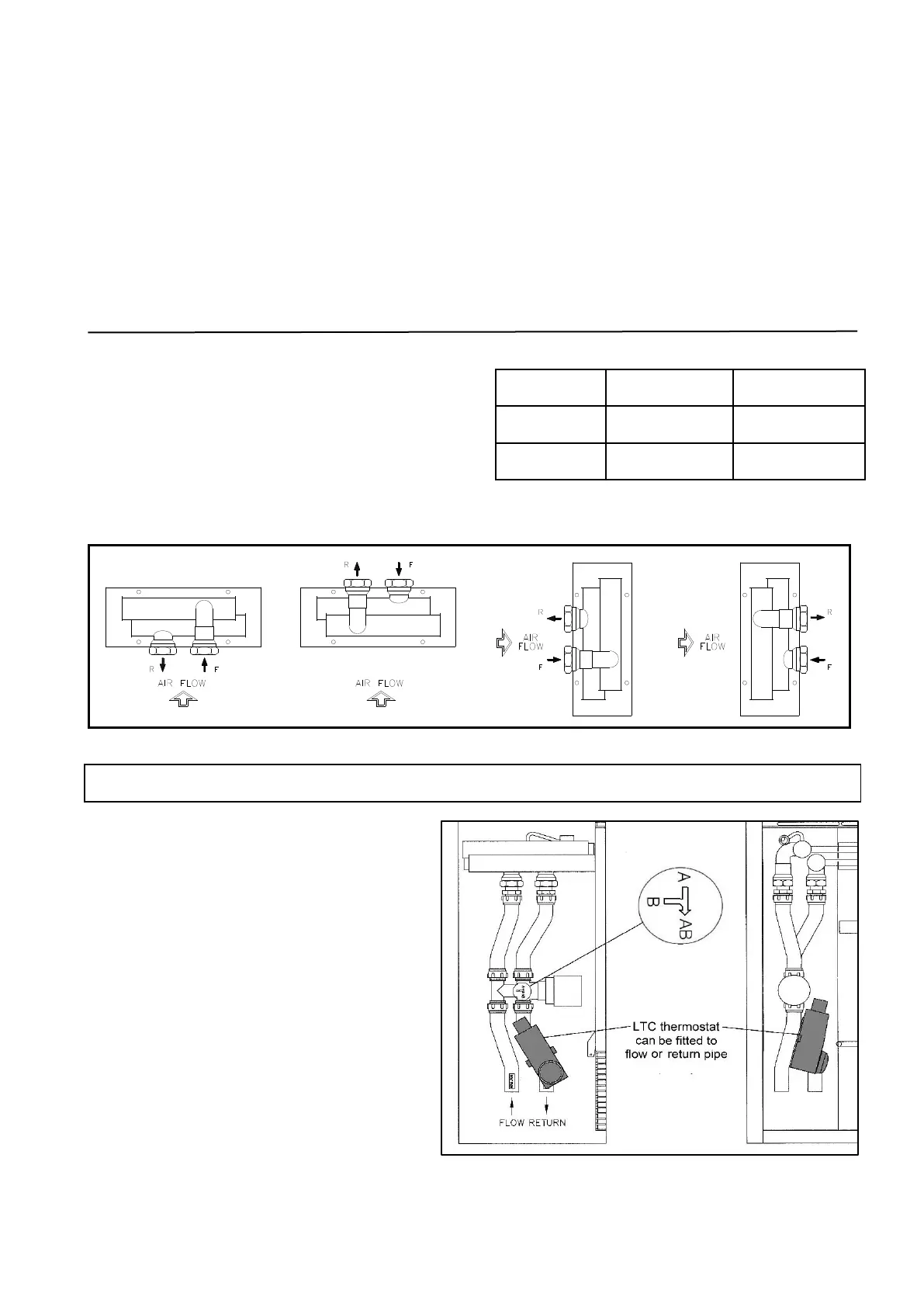
Diagram 7: Hot water coil connections, as viewed on the header/connection end of the coil.
NOTE: For correct operation, the back face of the Type 2 adjustable low temperature cut-off
thermostat needs to be in contact with a straight length of pipe approx. 100mm.
Avant Garde & LST Heaters
Avant –Garde and LST heaters are supplied
with controls valves which automatically shut
off the water flow when the fan is not
running.
Depending on the model and coil
arrangement supplied, the valves may be
supplied loose with special pipework for
fitting on site (see Diagram 8).
Flow and return connections must be
connected as shown in Diagram 8. The
diagram shows 4 port valve arrangement (2
port valve similar), with the LTC position
indicated.
Diagram 8: Control valve and LTC fitting locations
 Loading...