15
Schematic 1. Schematic indications for the control
of 2 independent loads, such as for example 2 bulbs
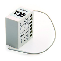
Terminal Board Connections:
1 – Local channel 1 input
(active when connected to 4)
2 – Local channel 2 input
(active when connected to 4)
3 – power supply (neutral or ”–“)
4 – power supply (line or “+”)
5 – common of relay contacts
6 – channel 1 n.o. output contact
7 – channel 2 n.o. output contact
Local inputs:
- 2 switches
or
- 2 buttons
2 resistive loads 230V ~
1250W Max each
Line 230V ~
DL1 Led
P1 Key
Neutral
Schematic 2. Schematic indications for the control
of a single-phase asynchronous motor
Terminal Board Connections:
1 – Local channel 1 input
(active when connected to 4)
2 – Local channel 2 input
(active when connected to 4)
3 – power supply (neutral or ”–“)
4 – power supply (line or “+”)
5 – common of relay contacts
6 – channel 1 n.o. output contact
7 – channel 2 n.o. output contact
Local inputs:
- 2 switches
230V single-phase
asynchronous motor
Max 500W
Line 230V ~
DL1 Led
P1 Key
Neutral
WARNING
ma k e s u r e t h e c o n n e c t I o n s a r e c o r r e c t b e f o r e p o w e r I n g t h e m o d u l e : I n c o r r e c t c o n n e c t I o n m ay d a m ag e t h e e q u I
-
p m e n t a n d c au s e d a n g e r t o p e r s o n a l s a f e t y .
 Loading...