L I V I
Operating instructions and warnings
8
WARNING Wrong assessment of impact forces may cause
serious damage to people, animal and things. DEA System re-
minds all personnel that the installer must ascertain that these
impact forces, measured according to EN 12445 prescriptions,
are actually below the limits indicated by EN14453 regulation.
WARNING In line with EU Directive 2002/96/EC for waste
electrical and electronic equipment (WEEE), this electrical pro-
duct must not be disposed of as unsorted municipal waste.
Please dispose of this product by returning it to your local
municipal collection point for recycling.
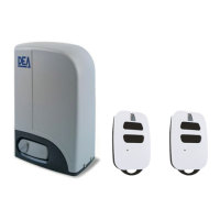
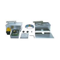
3 MODELS AND CONTENTS
OF THE PACKAGE
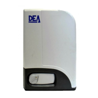
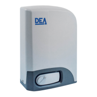
The name LIVI identifies a series of electromechanical opera-
tors with different features as to motor and control board power
supply voltage, range of built-in or external control board and
mechanical adjustment of force, electronic clutch and built-in
limit switch. DEA System articles in the series are listed in the
“AVAILABLE MODELS” table. LIVI is completed by a set of acces-
sories listed in the “PRODUCT ACCESSORIES” table.Inspect the
“Contents of the Package” on Page 30 and compare it with your
product for useful consultation during assembly.
4 OPERATING INSTRUCTIONS
In compliance with Directive 2006/42/CE Enclosure I, Point
1.7.4.
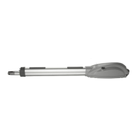
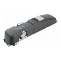
4.1 Product description
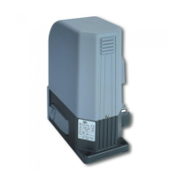
LIVI is an electro-mechanical operator designed for the
automation of sliding gates. LIVI is basically made up of a
mechanical gear motor (vedi F1 pag. 30) rotating the draft
gear that, in association to a properly installed rack, converts
the circular movement of the gear motor into straight-line
movement, thus allowing the gate to move in its own slide.
4.2 Technical data
See the “TECHNICAL DATA” table.
4.3 Labelling information
Part of the summarised data for the CE label are listed in the
label applied to the product (see Position F5, Page 30); the data
regarding the seller are found in the enclosed Warranty, whi-
le “Indispensable Operating Safety Elements” are found under
Point “4.2 Technical data”.
“PRODUCT ACCESSORIES” table
Article
Code
Description
111
619000
Nylon rack
112
126001
Zinc plated rack
22x22
113
126000
Zinc plated rack
30x12
460
619010
Foundation base
to be cemented
“AVAILABLE MODELS” table
Article
Power
supply
tension
Capacity
(kg)
Control
board
Force
adjustment
Encoder
6RR 230 V ~ 600 YES ELE YES
9RR 230 V ~ 900 YES ELE YES
805RR 230 V ~ 800 YES ELE YES
5/24RR/F 230 V ~ 500 YES ELE NO
8/24RR/F 230 V ~ 800 YES ELE NO
403E 230 V ~ 400 YES ELE NO
803E 230 V ~ 800 YES ELE NO
“TECHNICAL DATA” table
403E
6RR
803E
9RR
805RR
5/24RR/F
8/24RR/F
Single-phase power supply voltage (V)
380/220 V ~ ±10% (50/60 Hz) - 24 V
230 V ~ 230 V ~ 230 V ~ 24 V
Absorber power (W) 320 450 350 80 110
Built-in capacitor (µF) 8 12,5 -
Work cycle
45s-1s-45s x5
times
90 min PAUSE
45s-1s-45s x8
times
90 min PAUSE
45s-1s-45s x6
times
100 min PAUSA
45s-1s-45s x5
times
5 min PAUSA
Max Thrust (N) 340 490 275 210 260
Weight of product (Kg) 11 12,5 12
Operating temperature range (°C) -20 ÷ 40
Motor thermal protection (°C) 140° 160° -
Speed (m/min) 10 10,8 10 8,2
Degree of protection IPX4
Overall dimensions see F2 Pag. 31

 Loading...