67
sliding gate Swing gate overhead door barriers
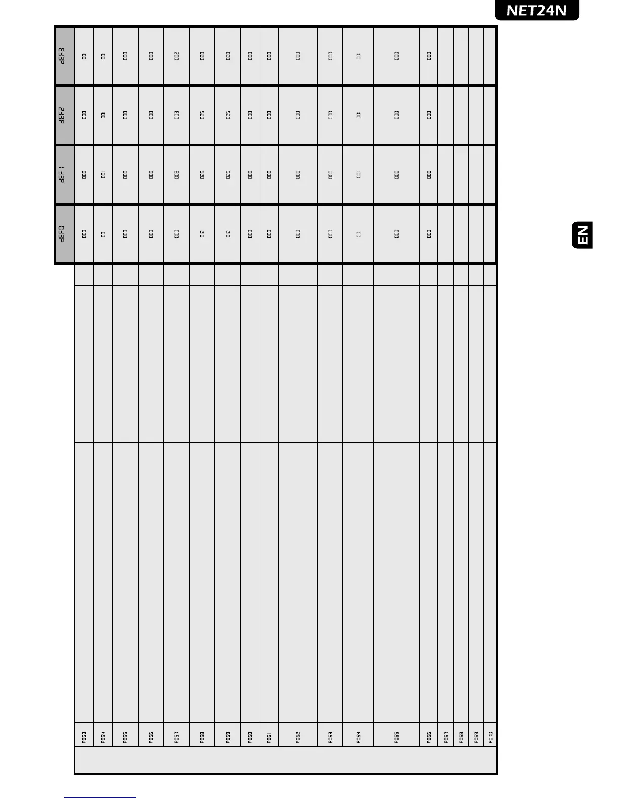
OPERATING PARAMETERS
Searches for end of stroke while opening too: when activated, operators stop only at their arrival et the end
of stroke, also while opening.
• 000: Stop when opening on a memorized point
• 001: Stop when opening on the end of stroke
“soft start” function: motors accelerate gradually until they reach the set speed, avoiding sudden departures • 000: “soft start” deactivated
• 001: “soft start” activated
Adjust the inversion on obstacle period (detected by internal anti-crushing sensor or by the safety input when
activated): If = 0 it makes a complete inversion, if> 0 indicates the duration (in seconds) of the run, after
inversion resulting from detection of an obstacle during the opening.
• 000: inversione completa su ostacolo
• >000: durata dell’inversione su ostacolo
(1sec……………..10sec)
Adjust the inversion on obstacle period (detected by internal anti-crushing sensor or by the safety input when
activated): If = 0 it makes a complete inversion, if> 0 indicates the duration (in seconds) of the run, after
inversion resulting from detection of an obstacle during the closing.
• 000: complete reversal on obstacle
• >000: duration of reversal on obstacle
(1sec……………..10sec)
Facilitation manual release: If≠0, after detecting the locking stop, the engine reverses for a brief time to release
the pressure on it, and thus facilitate the manual release. The set value shows the length of the inversion. If=0
function disabled
• 000: facilitating release disabled
• >000: facilitation activated with release time equal to:
(0x25ms……………..20x25ms)
Margin adjustment of the opening stroke: adjusts the duration of the last stretch of the race during which any
obstacle is interpreted as a stroke, stopping the operator without executing the inversion. The value set indicates
the number of revolutions of the rotor.
1...................................255
Margin adjustment of the closing stroke: adjust the duration of the last stretch of the race during which any
obstacle is interpreted as a stroke, stopping the operator without executing the inversion. The value set indicates
the number of revolutions of the rotor.
1...................................255
Operators force adjustment at stroke arrival - If = 0, setting off (the force value on the stroke is calculated
automatically) - If ≠ 0, indicates the value (expressed in% of the max value ) of the force exerted on the stroke.
0%tot…...........................100%tot
“Energy saving” mode: If=1 after 10sec of inactivity, the control panel turns the 24V outputs and the display
off that will be turned on at first command received (use recommended battery-powered and / or solar panel).
• 000: “Energy saving” not active
• 001: “Energy saving” active
Electric-lock operating: if =0 electric-lock art. 110, if=1 24V output commanded by ELOCK_IN input in
impulsive mode, iF=2 24V output commanded by ELOCK_IN input in step-by-step mode, If>2 24V output
commanded by ELOCK_IN input in temporized mode (the set value indicates the delay of turning off expressed
in sec.
• 000: “Electric-lock art. 110 output
• 001: “24V d.c. max 5W Impulsive output
• 002: “24V d.c. max 5W Step-by-Step Output
• >002: “24V d.c. max 5W Temporized output
(3sec………………255sec)
Run direction inversion: If=1 automatically reverses the outputs open/close of the operators and any opening/
closing limit switches inputs, avoiding having to manual change the wiring when installing the operator in an
inverted position.
• 000: “Standard installation”
• 001: “Inverted installation”
Multiplier operations-counter: Multiply the number of operations after which the total operations-counter will
be updated.
To view the values, refer to the section “Visualisation of inputs and operations-counter status”.
• 000: “x100
• 001: “x1000
• 002: “x10000
• 003: “x100000
Maintenance Operations-counter: if = 0 reset the counter and disables the intervention request , if> 0 indicates
the number of operations (x 500) to be made before the control panel executes a 4 second additional pre-flash
to indicate the need of maintenance.
i.g.: If P064 = 050, operations number = 50x500 = 25000 operations
Warning: Before you set a new value of the counter-manoeuvres maintenance, the same must be reset by
setting P065= 0 and only later P065 = “new value”.
• 000: “Request Maintenance disabled
• >000: “Number of operations (x 500) for required
maintenance
Selection of operating flashing light output: If=0 intermittent flashing light output;
If=1 Fixed flashing light output (for flashing lights with intermittent interior circuits).
• 000: “intermittent flashing light output
• 001: “fixed flashing light output
Unused parameter
Unused parameter
Unused parameter
Unused parameter
 Loading...