S P A Z I O
Operatinginstructionsandwarnings
13
WARNINGTheuseofsparepartsnotindicatedbyDEA
Systemand/orincorrectre-assemblycancreaterisktopeople,
animalsandpropertyandalsodamagetheproduct.Forthis
reason,alwaysuse onlythepartsindicatedbyDEA System
andscrupulouslyfollowallassemblyinstructions.
4.6 Training
After installation and setting, the correct operation of the
completeautomatismmust becarefullyillustrated tothefinal
user.TheSPAZIOgateoperatorrequirescarefulinstructionon
thereleasemechanism(see“Enclosures”)inparticularandthe
respectivemaintenanceschedule(seePoint4.5.6.).
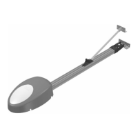
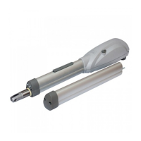
WARNING Awareness of the operation of the SPAZIO
releasemechanism(seeF9Page48)isessentialforallusers
oftheautomatismbecausethefailuretousethedevicequic-
klyduringemergenciescanjeopardisepeople,animalsand
property.EnclosureItotheseinstructions,whichtheinstaller
isrequiredtodelivertothefinaluser,illustratesoperationand
canbedetached.
4.7 Inappropriate use
Chapter“4.4Appropriateconditions ofuse”describesthe
conditionsforwhichtheproducthasbeendesignedandtested.
Theproductmustneverbeusedforotherpurposes.
WARNINGTheuseoftheproductunderunusualcondi-
tionsnotforeseenbythemanufacturercancreatesituations
ofdanger,andforthisreasonalltheconditionsprescribedin
theseinstructionsmustberespected.
5 WIRING AND CONTROL
BOARD PROGRAMMING
5.1 Wiring and terminal board connections
Connecttothepowersupply230V~.±10%50Hzthrough
amultipoleswitchoradifferentdevicethatcanensuremulti
poledisconnectionfromthepowersupply,withacontactope-
ningof3mm.Akeallconnectionstotheterminalboardandre-
membertoshort-circuit,whenevernecessary,allunusedinputs.
(Seetable1terminalboardconnectionandpage43basicand
completewiringdiagram)
5.2 Programming
Aftermakingallconnectionstotheterminalboard,rememberto
short-circuit,wheneverneeded,anyunusedinput(see“connec-
tiontothecontrolboard”)andpowerthecard:onthedisplay
youwillreadforafewseconds“rES-”followedbythesymbol
“----”whichstandsforgateclosed.
•• Visualisation of inputs status
Pressonthe“OK”keytocheckifallinputshavebeenproperly
connected.
FCA
PED/CHIUDE
START
FCC
FOTO
STOP
SIC
Bypressingonthe“OK”keywhenthecontrolboardawaitsfur-
ther instructions (“----”), the display shows some vertical seg-
ments: each one of them is associated to one of the control
board inputs (see the picture above). When the segment is
lighteditmeansthatthecontactassociatedtoitisclosed,on
thecontrary,whenitisswitchedoffthecontactisopen.Youcan
Centrale724RR
SPAZIO 702S
Centrale124RRZ
SPAZIO 703S
Table 1 Terminal board connection
1-2
24 V 1-2 24 V 24 V transformer power supply input (faston BLU)
/ 3-4
24 V Batt 24 V battery power supply input (Follow carefully polarity indications)
/
5-6
LC/SCA
Free contact max. capacity 5 A : this contact can be used to control an open gate war-
ning light (P27=0) or a courtesy lamp (P27≠0)
13-14
LAMP
7-8
LAMP
Flashing light output 24 V max 15W art. Lumy 24S The intermittent output does
not demand the use of a flashing light card.
13
COM 9 COM Common safety devices / Connection of motors metallic parts
13-12
+24VAUX 9-10
+24VAUX
+24 V power supply output for auxiliary circuits and uncontrolled safety devices To
be used as power supply of any auxiliary devices, photocell receivers (in all cases), and
of safety devices when testing these latter before each operation
13-11
+24VSIC 9-11
+24VSIC
+24 V power supply output for controlled safety devices. To be used as power
supply of photocell transmitters (in all cases) and of safety devices when testing these
latter before each operation
3-4
12-13
Motor output 24 V max 70W
J3 14
FCA N.C. input limit switch while opening.
J3 15
FCC N.C. input limit switch while closing.
5
START 16 START N.O. open input. If activated, it opens or closes both motors. It can work in “reversal”
mode (P25=0) or “step-by-step” mode (P25=1)
6
CHIUDE 17 PEDON PEDESTRIAN/CLOSE N.O. input. If it is set off it may: partly open the door (If P030>1);
close the door (If P030=1); close the door in all cases (If P030=0)
7
STOP 18 STOP N.C. stop input. If activated, it stops the movement of both motors during any opera-
tion. If unused, short circuit to common
8
FOTO 19
FOTOC
N.C. Photocell input. In case of activation it reverses the movement only while closing
(P26=0) or it reverses the movement while closing and stops while opening (P26=1). If
unused, short circuit to the common
9
SIC 20
SIC
N.C. leaf safety device input. In case of activation it reverses the movement (P18=0) or
it stops it (P18=1). If unused, short circuit to the common
10
COM 21 COM Common inputs
15
22 Aerial ground input
16
23
Aerial signal input
M M
 Loading...