EasyManua.ls Logo

Deca SM C36T - Page 8

Deca SM C36T
Print Icon
To Next Page IconTo Next Page
To Previous Page IconTo Previous Page
Loading...
950976-00 04/05/18
To stop charging the battery. In the following order, cut off the
power supply, remove the clamp from the bodywork or the
negative (-) terminal, and remove the clamp from the positive
(+) terminal.
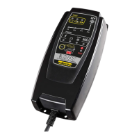
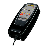
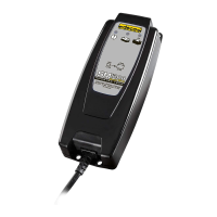
Battery charger description Mod.1 / 2
Control and signal LEDs - Fig.1
 “Set”
 
 
 


 
 
 
 
Charging a battery
¾ Connect the red clamp (+)     
and the black clamp (-)  
”Test” 

¾ Plug the plug into the socket to begin charging.
L “D” LED (red)

the connection.
¾ Use the “Set” key to select the charging program desired
Fig.2.
L
14.7 Volt charging

   

EQUALIZATION 

       
     
battery increases.
    

SUPPLY at constant 12,0 Volt 


          
drop.
L     

L 

“SUPPLY”

Charging phase Fig.2
Phase 1
       
        
“E0%”
Phase 2


“E0%”
Phase 3

“E 25%”; “E50%” permanently

Phase 4

“E75%” 
Phase 5

“E75%”
Phase 6
“E75%”

Phase 7
       
          
“E100%”
Phase 8



“E100%”
Charging Errors
Led “C”       
battery all along the charging cycle.
Led “C”+”E0%”     
replacement may be necessary.
Led “C”+”E0%” permanently illuminated = the battery
    
be necessary.
Led “C”+”E 25%” permanently illuminated = the capacity

a short-circuited cell.
Led “C”+”E0%” permanently illuminated = the battery

necessary.
Led “C”+”E75%” permanently illuminated = the current

short-circuited cell.
L       

L 

internal temperature becomes too high.
     


Related product manuals