DA2 Series Dehumidifier Owners Manual
Startup Adjust Expansion Valves
26 Dectron, Inc. November 2009
Data subject to change without notice.
Be sure that the blower overload device (if any) and the compressor(s) overload device(s), if any, are in the
RUN position. See Startup - Pre-Startup Adjustments.
Be sure the ENABLE switch is ON.
Some units may have a remote enable switch (by others) installed under
Installation - Wiring. In this case, be sure the switch is ON.
The blower should run unless
(a) the space temperature is less than 35°F (1.7°C), or
(b) the defrost timer is in defrost mode.
Defrost mode may last up to 10 minutes.
The compressor should run if the blower is running and if the humidistat set
point is less than the relative humidity of the air in the space.
If necessary, the humidistat set point can be reduced a little to cause the
compressor to run.
Carefully read and understand the warnings, cautions, and notices on the preceding page.
Be sure that the room temperature is between 40°F (4.4°C) and 80°F (27°C), or as shown on the unit
nameplate. (See Product Description - Unit Nameplate).
NOTICE
Risk of damage to equipment
The compressor should not be forced to run by reducing the
humidistat set point more than 10% below the set point
shown on the unit nameplate.
MODEL #: DA2-024-8
SERIAL #:
I.D.
T
575 V ac , 3 ph, 60 Hz
COMPRESSOR
50. 0
LRA
7.9
RLA
BLOW ER MOTOR
2
HP
2.4
FL A
MC A
13
A MAX. FUSE/CK T. BKR.
20
A
REFR IGERAN T TYPE
FACTORY CHARGE
15.5 lbs
AIR VO L U ME
3600 - 4000
CFM
BELT SIZE
WIRING DIAGRAM
DA2-W-024-021 AE Rev.5
REFRIGERANT DESIGN PRESS URES: HIGH/LOW 300 /150 PSIG
CERTIFIED TO STD CAN/CSA -
C22.2 NO. 236
FABRIQUÉ AU CANADA / MADE IN CANADA
POOL # 1: ft² POOL # 3: ft²
E.W.T.: ° F E.W.T.: °F
POOL # 2: ft² POOL # 4: ft²
E.W.T.: ° F E.W.T.: °F
AIR T E MP .:
60
°F R.H.:
60
%
R-22
15. 5
lbs
OIL T O BE ADDE D AT START- UP
oz
OIL TYPE
MAX. LENGTH OF REF. LINES (ONE WAY) ft
BETWEEN D.O.T. & REMOTE CONDENSER:
LINE S IZE:
AIR COOLED COND. MODEL #:
HOT GAS: i n
LIQUID: in
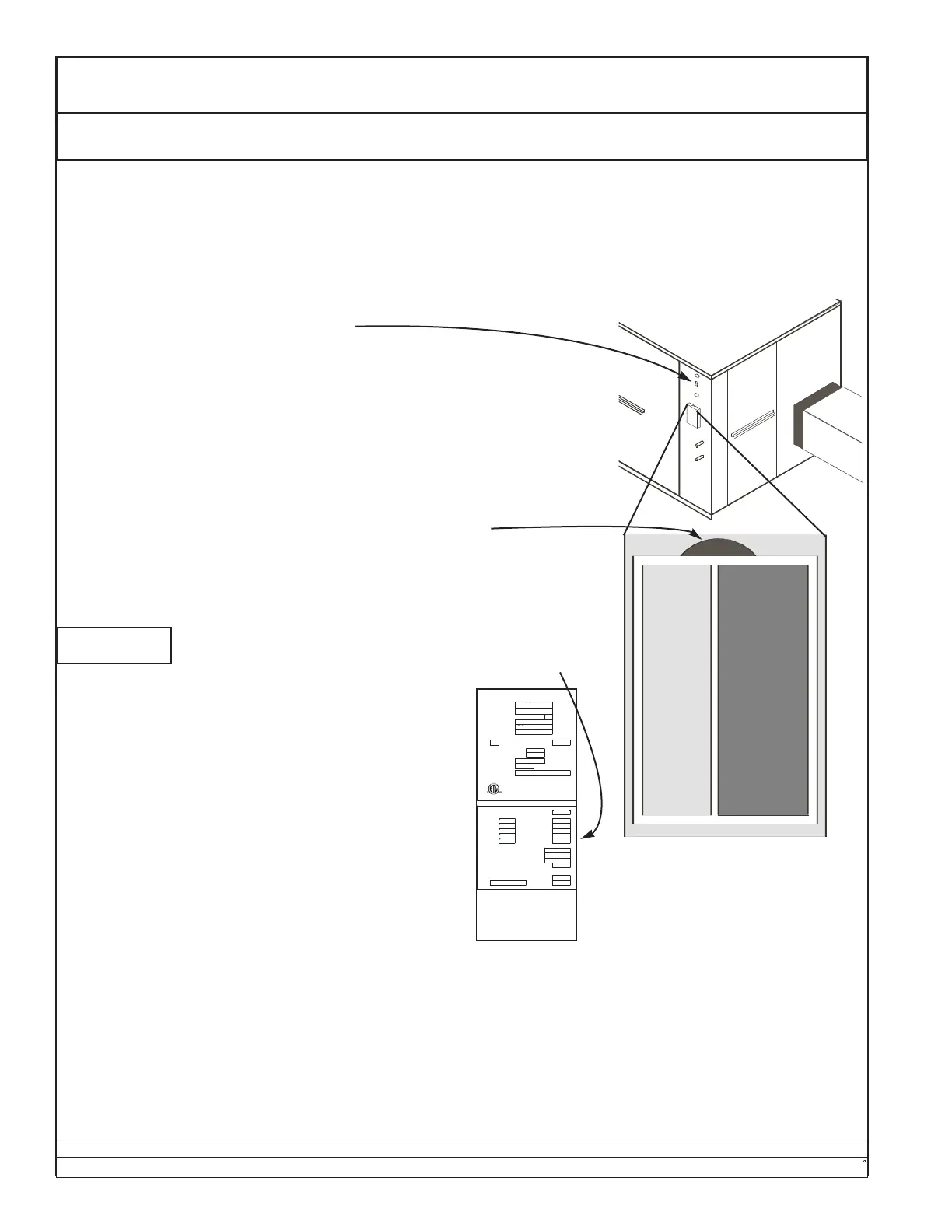
NOTE: In order to adjust the expansion valve
correctly, the space temperature and relative
humidity should be as near the normal conditions as
possible.
Samples
Actual appearances
may vary.
1. Continue to operate the unit for at least 20 minutes, monitoring the compressor-discharge temperature. Stop
operation if the discharge temperature exceeds 225°F (107°C).
2. After 20 minutes of compressor operation, and at least 10 minutes after the termination of any defrost cycle,
check the refrigerant sight glass.
If there are bubbles in the sight glass, slowly add the type of refrigerant shown on the unit nameplate until the
bubbles clear, then add one more pound by weight. NOTE: Do not add liquid refrigerant to a suction
access valve. If refrigerant has been added, return to step 1.
3. If the sight glass has been clear for at least 20 minutes, adjust the expansion valve(s) to cause the compressor
discharge temperature to agree with the charts on the following page.
 Loading...